Hi Don,
Correct.
When simulating a bass-reflex system in AkAbak you will need to add an "inside" end correction to the Hornresp Lpt value. The AkAbak Helmholtz Resonator tool may be of some help in this regard.
Hopefully the Hornresp prediction will be reasonably close to your measured results. You may find however that it is necessary to fine-tune your constructed system by altering the port tube length or enclosure volume slightly to get the exact Helmholtz resonance frequency as predicted by Hornresp. This is because Hornresp assumes an idealised configuration as shown in the schematic diagram, whereas in practice this is unlikely to be the case.
Incidentally, Hornresp uses a slightly more accurate model than WinISD so if you are comparing results with that program you may notice some slight differences") .
.
Kind regards,
David
In summary, if I build an enclosure with the port length as specified by Hornresp, it should measure similarly to the simulated enclosure. But in AkAbak, I have to manually add one end correction to the length provided by Hornresp in order to get a correct simulation.
Correct.
When simulating a bass-reflex system in AkAbak you will need to add an "inside" end correction to the Hornresp Lpt value. The AkAbak Helmholtz Resonator tool may be of some help in this regard.
Hopefully the Hornresp prediction will be reasonably close to your measured results. You may find however that it is necessary to fine-tune your constructed system by altering the port tube length or enclosure volume slightly to get the exact Helmholtz resonance frequency as predicted by Hornresp. This is because Hornresp assumes an idealised configuration as shown in the schematic diagram, whereas in practice this is unlikely to be the case.
Incidentally, Hornresp uses a slightly more accurate model than WinISD so if you are comparing results with that program you may notice some slight differences
.Kind regards,
David
Last edited:
Thanks, David.
I plan to keep the end correction as a separate term rather than merging it with the physical length. There's less chance for error when translating the design back to sawdust.
I'm already using the Helmholtz tool as part of the process:
- Simulate a standard reflex enclosure.
- Divide the box 2/3 and 1/3.
- Change the port (with the tool) to resonate the 2/3 box at the same frequency as the original box.
- Join the two boxes with one such port, and port both boxes to the outside with two more such ports.
There is a slight "fiddle factor" in the process, in that the resonance frequencies for the 2 enclosures are supposed to be slightly different than that for the original enclosure. Part of the reason for modelling in AkAbak is because I want to investigate and see if the "fiddle factor" was required because the original design process had end correction "embedded" in some way.
I'm mainly interested in DCR designs because of the fashion for tall, thin, spousally acceptable enclosures. The DCR design reduces the problem of quarter-wave resonances falling in the passband.
I've never used WinISD. I use Unibox and Brian Steele's "Ported" spreadsheets. I have noticed slight differences between Unibox results and Hornresp results.
There is no substitute for RTFM.
I have managed to summarise the rules for end correction in AkAbak. They are as follows:
- For a port (duct) connected to a duct (two ducts of different area connected),
AkAbak does not add end correction.
- For a port (duct) connected to an enclosure, AkAbak adds an end correction to the
end connected to the enclosure.
- For a port (duct) with a radiator attached to one end, the radiator element
provides the end correction for that end.
In summary, when simulating a reflex system in AkAbak using an Enclosure and a Duct (port), the specified length for the port is the physical length, as it is in Hornresp.
This highlights a possible inconsistency between Hornresp and AkAbak.
When exporting a reflex enclosure, Hornresp models it as a large duct (the enclosure) connected to a small duct (the port). The duct length specified for the port is the physical length (length used for simulation in Hornresp, minus end correction).
In AkAbak, this length is thus too short for simulation, because AkAbak does not add end correction in this case. A single end correction has to be manually added to obtain the same results as the Hornresp simulation.
If Hornresp were to export the enclosure as an Enclosure element, no additional end correction would be required. The Enclosure element does allow specifying the major enclosure length, so the length-related resonances of the enclosure are included in the simulation results.
Do I understand it correctly yet?
Last edited:
Incidentally, Hornresp uses a slightly more accurate model than WinISD so if you are comparing results with that program you may notice some slight differences
I can vouch for this as I have been comparing the two for almost a year. Hornresp tends to be more accurate when you realize exactly what you are simulating.
Do I understand it correctly yet?
Hi Don,
Seems okay to me.
I have no plans to export "Enclosure" elements to AkAbak, though
.Kind regards,
David
try using one of the virtualization methods like vmware fusion on a mac to run windows. This will work for sure but requires at least a windows lizense...
Wine seems to be somewhat ported to the mac from linus, so there myght be a possibility, too, I didn´t try it out though.
One last alternative I tried a few weeks ago is reactos, wait a second, I try again...
Oh, recent reactos running under vmware seems to work with recent hornresp, at least I could simulate the default project... Interesting. This sure is something worth investigatin further - I am surprised, it didn´t work last time...
If you like, I will compile something in order to bundle a package "hornresp on any PC without any windows-license....".

edit: hm,seems to crash sometimes after a few minutes.
Wine seems to be somewhat ported to the mac from linus, so there myght be a possibility, too, I didn´t try it out though.
One last alternative I tried a few weeks ago is reactos, wait a second, I try again...
Oh, recent reactos running under vmware seems to work with recent hornresp, at least I could simulate the default project... Interesting. This sure is something worth investigatin further - I am surprised, it didn´t work last time...
If you like, I will compile something in order to bundle a package "hornresp on any PC without any windows-license....".
edit: hm,seems to crash sometimes after a few minutes.
Attachments
Last edited:
im not good at computers.
i dont risk virus etc easily.
i dont risk virus etc easily.
try using one of the virtualization methods like vmware fusion on a mac to run windows. This will work for sure but requires at least a windows lizense...
Wine seems to be somewhat ported to the mac from linus, so there myght be a possibility, too, I didn´t try it out though.
One last alternative I tried a few weeks ago is reactos, wait a second, I try again...
Oh, recent reactos running under vmware seems to work with recent hornresp, at least I could simulate the default project... Interesting. This sure is something worth investigatin further - I am surprised, it didn´t work last time...
If you like, I will compile something in order to bundle a package "hornresp on any PC without any windows-license....".
edit: hm,seems to crash sometimes after a few minutes.
I'll summarise it like this, then.
When Hornresp exports a vented enclosure design in AkAbak format, it models it as a large Duct (the enclosure) attached to a small Duct (the port). Therefore, end correction needs to be added to the internal end of the small Duct in the AkAbak model to simulate the same as the Hornresp model. The standard "add 0.425 * the port diameter" is suggested.
For a long version of this, see here:
When Hornresp exports a vented enclosure design in AkAbak format, it models it as a large Duct (the enclosure) attached to a small Duct (the port). Therefore, end correction needs to be added to the internal end of the small Duct in the AkAbak model to simulate the same as the Hornresp model. The standard "add 0.425 * the port diameter" is suggested.
Hi Don,
Even though the Hornresp schematic diagram shows the port tube located external to the enclosure for the sake of simplicity, the simulation model actually assumes that the tube is positioned inside the enclosure, which is normally the case in practice.
Because the "inner" end of the tube does not terminate in a baffle, the end correction required is 0.306 * port diameter not 0.425 * port diameter.
Hornresp actually uses 4 / (3 * Pi * (2 ^ 0.5)) * port diameter, which is slightly more accurate than the 0.306 value suggested by AkAbak.
Kind regards,
David
Hi Don,
Even though the Hornresp schematic diagram shows the port tube located external to the enclosure for the sake of simplicity, the simulation model actually assumes that the tube is positioned inside the enclosure, which is normally the case in practice.
David,
Do you allow for the port tube volume in the enclosed volume? In other words, if someone builds an enclosure to the Hornresp calculated enclosure volume and port dimensions, will it resonate at the right frequency, or at a higher frequency due to the physical enclosure volume being smaller by the amount of the port volume?
Because the "inner" end of the tube does not terminate in a baffle, the end correction required is 0.306 * port diameter not 0.425 * port diameter.
The topology (port internal versus external) makes no difference for the total end correction. Either way, you have one end terminated in 2Pi space and the other terminated in 4Pi space. I believe that's why most programs use a lumped end correction of 0.732 * diameter. Actually, the AkAbak manual seems to "fudge factor" this. When talking about calculating the vent for a reflex form of the Enclosure element, it says:
If you specify the Helmholtz resonance fb= the program will evaluate the vent length Len=. In this case the length is evaluated with the Helmholtz-formula with a one-sided end correction of a duct mounted in an infinite baffle. The other side is loaded by the enclosure. Usually there is a good approximation of the inner loading due to the fact that standing waves are calculated (Lb=).
Hornresp actually uses 4 / (3 * Pi * (2 ^ 0.5)) * port diameter, which is slightly more accurate than the 0.306 value suggested by AkAbak. ...
It seems to me it should be possible to also account for the end topology (number of steradians) in this formula?
Hi Don,
The enclosure volume is given by Vrc and the port tube volume by Ap * Lpt, as shown in the schematic diagram. If the port tube is fully inside the enclosure then the total cabinet volume is actually Vrc + (Ap * Lpt). The Helmholtz resonance frequency will be correct.
As far as exporting to AkAbak is concerned, it is necessary to specify only the 4Pi value (0.306 * port diameter) because AkAbak will automatically include the 2Pi value (0.425 * port diameter) when either the enclosure element or a terminating radiator is used.
Hornresp already does this.
Kind regards,
David
Do you allow for the port tube volume in the enclosed volume? In other words, if someone builds an enclosure to the Hornresp calculated enclosure volume and port dimensions, will it resonate at the right frequency, or at a higher frequency due to the physical enclosure volume being smaller by the amount of the port volume?
The enclosure volume is given by Vrc and the port tube volume by Ap * Lpt, as shown in the schematic diagram. If the port tube is fully inside the enclosure then the total cabinet volume is actually Vrc + (Ap * Lpt). The Helmholtz resonance frequency will be correct.
The topology (port internal versus external) makes no difference for the total end correction. Either way, you have one end terminated in 2Pi space and the other terminated in 4Pi space.
As far as exporting to AkAbak is concerned, it is necessary to specify only the 4Pi value (0.306 * port diameter) because AkAbak will automatically include the 2Pi value (0.425 * port diameter) when either the enclosure element or a terminating radiator is used.
It seems to me it should be possible to also account for the end topology (number of steradians) in this formula?
Hornresp already does this
.Kind regards,
David
Hi Don,
The enclosure volume is given by Vrc and the port tube volume by Ap * Lpt, as shown in the schematic diagram. If the port tube is fully inside the enclosure then the total cabinet volume is actually Vrc + (Ap * Lpt). The Helmholtz resonance frequency will be correct. ...
Oh... yeah. The schematic shows the port as external, but the system volume at the top includes the port volume. I should be more observant.
Hornresp Version 28.50
Hi Everyone,
Hornresp Version 28.50 has just been released. Changes are:
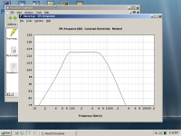
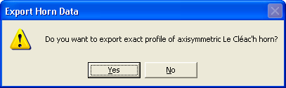
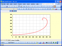
1. An option has been included to generate the "perfect axisymmetric profile" for a Le Cléac'h horn. See http://www.diyaudio.com/forums/multi-way/140190-jean-michel-lecleach-horns-114.html#post2619419 for further details.
2. Port tube end corrections are now included in exported AkAbak scripts, when appropriate.
Kind regards,
David
Hi Everyone,
Hornresp Version 28.50 has just been released. Changes are:
1. An option has been included to generate the "perfect axisymmetric profile" for a Le Cléac'h horn. See http://www.diyaudio.com/forums/multi-way/140190-jean-michel-lecleach-horns-114.html#post2619419 for further details.
2. Port tube end corrections are now included in exported AkAbak scripts, when appropriate.
Kind regards,
David
Attachments
Hi Everyone,
I'm beginning with Hornresp, trying different things.
When simulating a Bass Reflex and comparing the result with WinISD's (to be sure I'm doing ok), I don't get the same response... Could you tell me why ?
I model the same box with the same vent and get two different Helmoltz freq and two different response curves...
In HR, I did it with the Loudspeaker Wizard (wonderful feature by the way !!)
Perhaps all of this is already explain in this tread, but there's # 2000 messages ! If so tell me where !
Regards.
There can be many reasons - but the most important one: hornresp uses a completely different formula to calculate response and everything else.. hornresp´s model is way better than WinISD, it`s much more accurate.When simulating a Bass Reflex and comparing the result with WinISD's (to be sure I'm doing ok), I don't get the same response... Could you tell me why ?
I did some searching through this thread (that was fun) and have found some reference to this idea but am not really finding what I want to know.
What I am looking at is a quarter wave pipe (TL) with several identical drivers distributed along a portion of the pipe, not for smoothing necessarily but for convenience sake. I realize that HR can not simulate this directly (nor would it be reasonable to rewrite it to handle it) but what I am wondering is if one could not get a close enough approximation of the total response by simulating each position and averaging the results.
If the number of drivers is "n" and each segment area for the total pipe is S(x)total would one simulate each driver's contribution using segment areas of S(x)total/n (i.e. for 4 drivers pipe areas are 1/4 of what they will be in the final cabinet) or do each drivers contribution in the total pipe size?
Sorry if I missed this in earlier posts.
- Home
- Loudspeakers
- Subwoofers
- Hornresp