Yes, it does pass through the -1dB point at a lower frequency than the single speaker.Quote:
Hi Art,
The multiple speaker (green) trace does however pass through the -1dB point at a lower frequency than the single speaker (white) trace.
Kind regards,
David
Just as it does with two of the cabinets, in the same exact position, with one powered and the other shorted out, as is shown in post 1776.
The trace passing through the -1 dB point is due to the approximately one dB forward gain afforded by the larger frontal area of the two cabinets.
When that extra gain is taken into account, there is no change at all in the LF corner frequency of the two TH compared to one.
I had forgot that important little detail when I posted the chart in #1771.
Also note that no LF "bump" prior to the cut off frequency occurs as it does in the William Cowan 60 hertz tapped horn Hornresp simulation.
Art Welter
You don't seem to be thinking in terms of wavelength.Hi Art,
On your keystone TH design the mouth is a relatively small portion of the face of the box, and although the distance between them is not great I don't really think they are tightly coupled.
The wavelength of 35 Hz is about 32 feet long, 1/4 wavelength is 8 feet. The center to center distance between the mouth openings is only 26.5 inches, just over 2 feet.
The two cabinets have almost exactly 6 dB of gain when placed together and powered by the same voltage, if they were not actually "closely coupled", the gain would be less and the frequency response would be different.
The Keystone design mouth to frontal area ratio is a bit higher (smaller mouth compared to frontal area) than a DSL TH-115 or TH-118, or similar designs.
The DSL TH-115, with over 50% of the frontal area used by the mouth, also has no change in the LF corner when used in multiples.
The Keystone is similar in mouth to frontal area as the more usual tall single fold TH like the William Cowan 60 hertz tapped horn Hornresp simulation that David McBean chose to use as an example.
Art Welter
What limits the low end of the frequency response of a conventional horn loaded driver?
Horn length, Horn taper, Horn Mouth area.
The most difficult to get really low is Mouth area. This results in many conventional horns being truncated to reduce actual Mouth Area and as a side effect make the total volume much smaller than the full size horn.
Take a conventional horn loaded driver and ensure it has a taper to give 30Hz and a length to give 20Hz and a mouth to give 30Hz. Now truncate it because that horn was far too big for "my room".
The taper LF limit remains at 30Hz, halving the length of the horn increases the LF length controlled frequency to 40Hz and the reduced mouth area probably about 25% to 33% of the 30Hz horn will increase the LF frequency by about 1 octave, i.e. about 60Hz.
Now take two of those truncated conventional horns and stack them. The mouth area has doubled and the Mouth frequency moves down half an octave.
The doubled up truncated horn gains +3dB from the doubled power fed to the combination. It also gains +3dB @ ~ 60Hz due to the doubled driver horn area (moves twice as much air).
But at 45Hz the pair have gained a lot more than that +6db. That effect cannot be obtained with a pair of Tapped Horns. A Tapped Horn is not a Truncated Horn, it is a different animal.
I've done data outputs for rectangular horns where one pair of sides are the conical expansion onto which the curved sides are laid . The last data column there represents the length from throat to mouth measured along the wood of the conical pieces, ie. it is the axis measurement expanded by 1/cos(theta) where 'theta' is the half-angle
This wasn´t my question to David. I asked about the up and downside. About straight sides this is totally uninteresting as it is only a question of stretch-factor. Besides that, the tractrix made by Edgar using this technique is as long from the ideal as can be. Made with straight sides a radial horn would be far better. Have made a spreadsheet.
Last edited:
You don't seem to be thinking in terms of wavelength.
The wavelength of 35 Hz is about 32 feet long, 1/4 wavelength is 8 feet. The center to center distance between the mouth openings is only 26.5 inches, just over 2 feet.
The two cabinets have almost exactly 6 dB of gain when placed together and powered by the same voltage, if they were not actually "closely coupled", the gain would be less and the frequency response would be different.
The Keystone design mouth to frontal area ratio is a bit higher (smaller mouth compared to frontal area) than a DSL TH-115 or TH-118, or similar designs.
The DSL TH-115, with over 50% of the frontal area used by the mouth, also has no change in the LF corner when used in multiples.
The Keystone is similar in mouth to frontal area as the more usual tall single fold TH like the William Cowan 60 hertz tapped horn Hornresp simulation that David McBean chose to use as an example.
Art Welter
Hi Art,
You might use the system design function to come up with the aggregate mouth area needed to support 35Hz, then divide that across the intended number of bins per stack.
And hope that being within the prefered portion of a wavelength at the high cutoff gives you tight coupling.
This wasn´t my question to David. I asked about the up and downside. About straight sides this is totally uninteresting as it is only a question of stretch-factor. Besides that, the tractrix made by Edgar using this technique is as long from the ideal as can be. Made with straight sides a radial horn would be far better. Have made a spreadsheet.
Hi Lars,
It sounds like you are already have it figured out now? The method I would use in a spreadsheet would be to do a Hornresp export of the area in 1cm increments and then divide that by the width or height of your planned expansion to derive the unknown dimension.
About Export. when printing out horn data I guess "Side length" is for cutting a template for a square horn. In other words it is width with stretch factor added.
If I have understood everything right there will be no problem when doing a square horn but if it is for rectangular there are no data for top/ bottom. Anything you can add?
Hi Lars,
You understand correctly
") .
.Template lengths for the left and right sides of a square or rectangular horn are exported when the Width Flare is specified as Con or Exp, but not when the Width Flare is specified as Uni.
Template lengths for the top and bottom sides of a square or rectangular horn are not exported.
Kind regards,
David
When you model a tapped horn with 4 drivers by multiplying the cross-sections of a single driver TH by four, Hornresp gives you the same SPL response that you get from using the multiple speakers output on the single version of that tapped horn (provided you make the approriate adjustments in Eg).
Hi Oliver,
Your comment above prompted me to do some further validation tests.
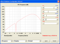
The SPL response of two William Cowan 60 hertz tapped horns connected in parallel and radiating into 2 x Pi half-space was compared against the results for a single similar system radiating into 1 x Pi quarter-space, and also against the results for a single similar system with two drivers connected in parallel and the cross-sectional areas doubled, radiating into 2 x Pi space. Eg was set to 2.83 volts and Rg set to 0 ohms in all three cases.
The SPL predictions are identical for the three different configurations. This would suggest to me that there can’t be too much wrong with Hornresp tapped horn multiple speakers model
.Kind regards,
David
I tried comparing the results of my vent length equation (see The Subwoofer DIY Page - Port Calculations) against HornResp's predictions by simming a 80 litre volume that's being tuned to various frequencies with a 140cm^2 vent.
This first table shows the predicted lengths using my vent calculation:
20 Hz - 121.5 cm
30 Hz - 48.6 cm
40 Hz - 23.4 cm
50 Hz - 11.2 cm
60 Hz - 4.8 cm
70 Hz - 0.9 cm
This second table shows the lengths predicted by HornResp
20 Hz - 118.0 cm
30 Hz - 51.6 cm
40 Hz - 27.0 cm
50 Hz - 15.0 cm
60 Hz - 8.8 cm
70 Hz - 5.2 cm
It looks like HornResp is predicting longer vents are required to achieve the same Fb (except for 20 Hz). The difference between the lengths seems to vary from 4.3 cm down to 3.0 cm @ 30 Hz, suggesting that the end-correction factor that HornResp is not only slightly different, but also somewhat frequency-dependent.
Curiously enough, if my equation is predicting vent lengths that are longer than required (see vent tuning that suggests the calculated lengths might be just under 20% too long), that means that the vent lengths predicted by HornResp might even more inaccurate...
I tried comparing the results of my vent length equation (see The Subwoofer DIY Page - Port Calculations) against HornResp's predictions by simming a 80 litre volume that's being tuned to various frequencies with a 140cm^2 vent.
Hi Brian,
You obviously used a release of Hornresp older than Version 28.00 when doing your comparisons
.Kind regards,
David
Attachments
Last edited:
Hi Brian,
You obviously used a release of Hornresp older than Version 28.00 when doing your comparisons
Kind regards,
David
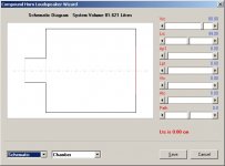
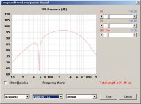
Actually I'm using version 28.00, but I was using a compound horn config and S5-S6 set to 140 cm^2 to simulate the "vent" (see images below). Shouldn't this produce the same results as using Apt and Lpt? The schematic is basically identical.
Attachments
Helmholtz freq
Hi David,
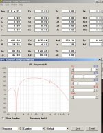
When trying to duplicate Brian's results from Post #1788 the nice little "Helmholtz freq is ...Hz" (your Post #1790) disappeared when going from Lpt 96.90 to Lpt 97.00. This is with the newest version of Hornresp (2830-110403). In an older version (2830-110124) this was the point where this display changed to "Ltc is 0.00cm".
Hadn't noticed that before.
Regards,
Hi David,
When trying to duplicate Brian's results from Post #1788 the nice little "Helmholtz freq is ...Hz" (your Post #1790) disappeared when going from Lpt 96.90 to Lpt 97.00. This is with the newest version of Hornresp (2830-110403). In an older version (2830-110124) this was the point where this display changed to "Ltc is 0.00cm".
Hadn't noticed that before.
Regards,
Attachments
I agree, not much wrong with the TH multiple speakers model, other than it does not agree with actual measurements of real cabinets in which the LF corner does not change in multiples.Hi Oliver,
Your comment above prompted me to do some further validation tests.
The SPL response of two William Cowan 60 hertz tapped horns connected in parallel and radiating into 2 x Pi half-space was compared against the results for a single similar system radiating into 1 x Pi quarter-space, and also against the results for a single similar system with two drivers connected in parallel and the cross-sectional areas doubled, radiating into 2 x Pi space. Eg was set to 2.83 volts and Rg set to 0 ohms in all three cases.
The SPL predictions are identical for the three different configurations. This would suggest to me that there can’t be too much wrong with Hornresp tapped horn multiple speakers model
Kind regards,
David
Art
I was using a compound horn config and S5-S6 set to 140 cm^2 to simulate the "vent" (see images below). Shouldn't this produce the same results as using Ap and Lpt?
Hi Brian,
Prior to Version 28.00, the results were the same. A tube specified by Ap and Lpt was assumed in all cases to act as a cylindrical horn, rather than possibly as a lumped air mass. Unfortunately this meant that predictions for conventional bass-reflex systems in particular, were not entirely accurate.
To address this shortcoming Hornresp now checks the Ap and Lpt dimensions and subject to certain conditions being met, assumes that the air in the tube is acting as a lumped mass. In such cases a Helmholtz frequency value will be given. Where the conditions are not met Hornresp assumes that the tube is acting as a cylindrical horn, as before.
When S5 and S6 are used, Hornresp assumes that the tube is always acting as a horn regardless of the S5, S6 and L56 dimensions.
As you have observed the results are different for the two cases.
With a bit of work I could probably make it so that the results for the two scenarios are consistent again, with the tube acting as a lumped mass rather than a cylindrical horn where appropriate - independent of how it is specified - but I am not sure that it is really worth the effort.
I guess I will have to think about it
.Kind regards,
David
Hi Oliver,
This is because the tube length relative to cross-sectional area is such that the tube now acts more as a cylindrical horn than as a lumped air mass - see my reply to Brian above.
I decided to remove the "Ltc is 0.00cm" message from this view because it is not really relevant and could be confusing to some users, since the throat chamber sliders are not present.
I'm impressed - you are very observant indeed.
Kind regards,
David
When trying to duplicate Brian's results from Post #1788 the nice little "Helmholtz freq is ...Hz" (your Post #1790) disappeared when going from Lpt 96.90 to Lpt 97.00.
This is because the tube length relative to cross-sectional area is such that the tube now acts more as a cylindrical horn than as a lumped air mass - see my reply to Brian above.
In an older version (2830-110124) this was the point where this display changed to "Ltc is 0.00cm".
I decided to remove the "Ltc is 0.00cm" message from this view because it is not really relevant and could be confusing to some users, since the throat chamber sliders are not present.
Hadn't noticed that before.
I'm impressed - you are very observant indeed
.Kind regards,
David
I agree, not much wrong with the TH multiple speakers model, other than it does not agree with actual measurements of real cabinets in which the LF corner does not change in multiples.
Hi Art,
I really don't understand why the results for multiple tapped horns should be any different to those for other speaker types.
Do you have an explanation for the difference - what reason(s) could there be for the "LF corner" not to move for multiple tapped horns, when apparently it does for all other speaker types?
Please excuse me for being a bit wary - at one stage a number of users believed that the Hornresp tapped horn diaphragm displacement predictions were also incorrect. Bjørn Kolbrek did some very careful and accurate test measurements to prove that this was simply not the case.
Kind regards,
David
Hi Lars,
Some observations...
For identical inputs, the calculated Hornresp and subbashorn.xls spreadsheet results are effectively the same. The formula used to calculate system Vas in your spreadsheet is an approximation only - that is why there are slight differences in our results.
The spreadsheet assumes that the Mmd value in Hornresp will be the same as the driver Mms value. This is not the case.
Your spreadsheet requires the user to initially nominate values for m, Fl and Fh and then manually optimise to achieve an acceptable result. Hornresp does this automatically.
Kind regards,
David
Hi David,
Moved this from the other thread as it for some reason is closed.
I admit the Spreadsheet is wrongly written about Mmd in the export to Hornresp. Mmd should best be calculated in Hornresp. So I will remove the speaker data and only export the horn and volume data. But as in Marshall Leach AES paper, Mms is what I use in the spreadsheet. Maybe some light should be spread about this. Checked the paper a few days ago as my speakerinterest was newborn.
I admit, when you use Fl and Fh from the spreadsheet the results are identical and should be. But the Design function forces you, what values to be used and that is where I found it less useful. My spreadsheet might be less userfriendly but really optimizes values directly with the T and Fl you choose.
About Vas to my knowledge is not an approximation as it relies on the same Small/Thiele formulas. But I have also a version where you input Vas and can´t see any difference. I have also checked the calculated Vas against many speakers and they seem to be right.
Last edited:
Hi Brian,
Prior to Version 28.00, the results were the same. A tube specified by Ap and Lpt was assumed in all cases to act as a cylindrical horn, rather than possibly as a lumped air mass. Unfortunately this meant that predictions for conventional bass-reflex systems in particular, were not entirely accurate.
To address this shortcoming Hornresp now checks the Ap and Lpt dimensions and subject to certain conditions being met, assumes that the air in the tube is acting as a lumped mass. In such cases a Helmholtz frequency value will be given. Where the conditions are not met Hornresp assumes that the tube is acting as a cylindrical horn, as before.
When S5 and S6 are used, Hornresp assumes that the tube is always acting as a horn regardless of the S5, S6 and L56 dimensions.
As you have observed the results are different for the two cases.
With a bit of work I could probably make it so that the results for the two scenarios are consistent again, with the tube acting as a lumped mass rather than a cylindrical horn where appropriate - independent of how it is specified - but I am not sure that it is really worth the effort.
I guess I will have to think about it
Kind regards,
David
Ah, I figured it was something along those lines.
Perhaps having HornResp give a warning that the "lumped mass" model might give better results once specific conditions are met might suffice. Or even an option to switch to the lumped-mass calculations (similar to the option to switch between Con, Hyp and Par calculations), might be enough.
Another approach might be a best-fit curve for the "end correction" that gives results more in line with the lumped-mass model when the conditions calls for it.
Bear in mind though that even the calculation of Fb for the lumped-mass model might be a little off, as emperical testing on another site suggests that the equations give values for Lv that may be as much as 20% too long. I aim to do my own emperical testing of predictions vs actual results once I get the opportunity, as that difference is a bit too much for my liking (unfortunately I'm way too busy these days to even look at the wood languishing in my garage awaiting my attention
).Finally, this might be pure coincidence, bit I've noticed that there is much closer alignment between the horn model and the lumped mass model when the space is switched to 0.5*PI. I don't know if that's useful or not.
Hi Art,
I really don't understand why the results for multiple tapped horns should be any different to those for other speaker types.
Do you have an explanation for the difference - what reason(s) could there be for the "LF corner" not to move for multiple tapped horns, when apparently it does for all other speaker types?
Please excuse me for being a bit wary - at one stage a number of users believed that the Hornresp tapped horn diaphragm displacement predictions were also incorrect. Bjørn Kolbrek did some very careful and accurate test measurements to prove that this was simply not the case.
Kind regards,
David
David,
I am far more an empiricist than a theorist, I only know what I have measured or have seen others measure. Thus far, I have seen no actual measurements indicating that the low corner changes on multiple TH, other than what would be accounted for by the increased frontal area multiple cabinets afford.
I have also confirmed that the Hornresp TH displacement predictions are correct, other than below Fb (Fc?) where the speaker suspension limits excursion to lesser values than predicted at high power, but that would apply to any design simulation.
Your response to Brian Steele in post 1794 may explain the difference between a TH and a regular horn far better than any explanation I could come up with.
It appears that TH as generally built may be more like two tubes acting as a lumped mass rather than a cylindrical horn.
TH-Tapped Horn, DDD-Dual Driven Duct, DLM-Dual Lumped Mass, name that cabinet....
Calling a tiny TH a horn seems to make about as much sense as calling a flute a trumpet, but once named, the name sticks whether it makes sense or not.
“Classic” horns drop at around 12 dB per octave below Fc, “classic” Theile-Small BR alignments drop at around 24 dB per octave below Fb.
Most TH below Fb (Fc?) seem to drop at an even steeper rate than TS BR alignments.
TH seem to share more in common with BR ( ducts with lumped air mass) than normal horns.
Like “TH”, BR cabinets low corner (F3) does not drop in multiples.
Art Welter
Your response to Brian Steele in post 1794 may explain the difference between a TH and a regular horn far better than any explanation I could come up with.
If that was the case, HornResp's impedance response predictions will not match real life measurements for THs. I can confirm that this is not the case - the predicted impedance response is a very close match to what I've actually measured.
- Home
- Loudspeakers
- Subwoofers
- Hornresp