I was initially going to use the LeCleac'h flare, it was suggested by another forum member to look at the Tractrix flare. I see the LeCleach flare is alot shorter and rounder. What is your opinion on each?
Hi Gregg,
As Lars points out, a 120 hertz Le Cléac'h horn terminating in a 90 degree mouth will be a little larger than the equivalent tractrix horn. Subjectively I would expect the performance of the Le Cléac'h horn to be marginally superior to that of the tractrix horn, but this is my opinion only - I am sure that others may disagree with me here
") .
.The difference in dimensions for the two horn options would be:
Tractrix flare:
S1 = 20.30
S2 = 6539.49 (mouth diameter = 91.25 cm)
L12 (Tra) = 117.78
F12 = 120.00
AT = 3.19
Fta = 90.00
Le Cléac'h flare:
S1 = 20.30
S2 = 11708.62 (mouth diameter = 122.10)
L12 (Lec) = 126.12
F12 = 120.00
T = 1.00
AT = 3.19
Fta = 89.81
(The Horn Segment Wizard tool was used to determine the above Le Cléac'h values).
The 120 hertz Le Cléac'h horn would be 8.34 cm longer than the equivalent tractrix horn, with the mouth diameter being 30.85 cm larger. This should result in a slightly "smoother" overall SPL response.
Kind regards,
David
Can you please expand on the above quote. I am still unsure what to choose for my round horns on the con, exp or uni drop down.
Hi Gregg,
The comment was offered before I knew that you planned to build a round horn
. It only applies to square or rectangular cross-section horns. Leave the Width Flare as the default "Con" - the height and width data so generated is not required for your round horn anyway.Kind regards,
David
I have found a good correlation between 0.5Pi and whatever I measured in a car.
Thanks Mark. I'm considering a new sub design for my car (a sort of isobaric design with a loading chamber to pull up the 80~ 100 Hz response a bit), so it would be nice if there's good correlation between the HornResp predictions and the measured response.
If I use HornResp to model in-car response for a particular subwoofer design, what parameter should I pay attention to? For example, should assume 0.5*PI or even 0*PI loading?
Hi Brian,
Setting Ang = 0.5 * Pi should give the closest approximation to in-car loading conditions. The predicted SPL response will not include any "cabin resonances" however.
Setting Ang = 0.0 * Pi would specify an infinite horn - not applicable in this case.
Kind regards,
David
The 120 hertz Le Cléac'h horn would be 8.34 cm longer than the equivalent tractrix horn, with the mouth diameter being 30.85 cm larger. This should result in a slightly "smoother" overall SPL response.
I agree on that. I have also made two more sims where I in the first changed the LeCleach Fc to get equal length of the horns and in the second case to get equal moutharea of the horns. In both cases the LeCleach looked smoother even if it in the latter case got a lot shorter.
Hi Mark and brsanko,
Thanks for your kind words. As you have probably gathered by now, I am a bit of a perfectionist - it can be a real curse sometimes
Kind regards,
David
David,
More gratitude and thanks for Hornresp.
It helped in designing my latest speaker cabinet, and furthered my understanding of what I have done wrong (and right) in some previous designs done without a simulation program.
In light of your continued efforts to make Hornresp even better, I thought you may want to address one aspect that does not match reality.
Tapped horns, unlike regular bass horns, do not have a lower corner frequency when used in multiples.
TH response in multiples does smooth out frequency response, and an overall 6 dB increase in SPL will occur with a pair given the same voltage as a single, but the low corner stays the same.
When multiple TH are simulated in Hornresp presently, the LF corner drops.
That is not consistent with actual measured results, and many folks are expecting the low corner to be lower in multiples, while it is not.
People who have built multiple TH frequently seem to mistake the overall gain increase for a lower frequency response.
Tom Danley ( the inventor who coined the term “tapped horn”) has mentioned in many posts the fact that TH's LF corner does not drop in multiples.
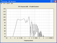
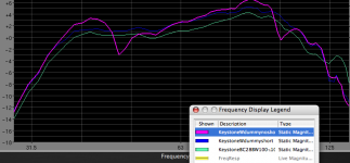
Ivan Beaver, presently working for Danley Sound Labs took the TEF measurements below right of a single and two DSL TH-115 outdoors, the results clearly show the increase of 6 dB with no LF corner change.
They also show an in room response at the NYC Pro Sound sub shootout, also using TEF, showing how that room changes the response.
I tested my Keystone TH, slightly larger than the DSL TH-115, the results of one vs. two are posted below. The same tests with the X2 results reduced by 6 dB more clearly show the LF response overlays almost exactly, other than some slight wiggles due to wind.
My outdoor tests used a Bruel & Kjaer 4004 microphone into a M-Audio Project Mix using Smaart V6 on a MacBook Intel Core 2 Duo.
If fixing the program error is not possible, or devilishly difficult, you may want to simply amend the TH instructions pointing out that the LF corner change in multiples does not actually happen.
Thanks again for a great program.
Art Welter
Attachments
Tapped horns, unlike regular bass horns, do not have a lower corner frequency when used in multiples.
Errrrrr WHAT???,
I think that what you and Tom share in common that is driving you both to the same result is that you both seem to be using a long path and small mouth in your TH's. This assumption on my part is based on my recollection of Tom mentioning that some designs would not benefit from mutual coupling in the way that a more conventionally sized exit mouth would.
If you design with mutual coupling in mind you will get a lower corner; you just have to account for it in the design by having enough mouth area coupling for the stack of bins to support the path length in your horns.
I tested my Keystone TH, slightly larger than the DSL TH-115, the results of one vs. two are posted below. The same tests with the X2 results reduced by 6 dB more clearly show the LF response overlays almost exactly, other than some slight wiggles due to wind.
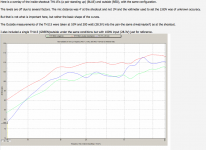
Hi Art,
The attached Hornresp screenprint compares the SPL response for a single William Cowan 60 hertz tapped horn (gray trace) against that for two similar horns connected in parallel (black trace). Eg has been adjusted accordingly to normalise the midband levels of the two traces. It seems to me that the results are really not that much different to those measured by you - the multiple speakers bass performance in each case is extended marginally.
I would be reluctant to modify the Hornresp multiple speakers model just to accommodate tapped horns
. The present model is very robust theoretically, and should be equally valid for any speaker type - it does however assume that multiple horn mouths are tightly coupled. Perhaps this is not actually the case with your test measurement setup.Kind regards,
David
Attachments
The horn mouths of my test and Ivan’s test were closely coupled, they show the LF corner has dropped perhaps 1 Hz going from one to two cabinets.Hi Art,
The attached Hornresp screenprint compares the SPL response for a single William Cowan 60 hertz tapped horn (gray trace) against that for two similar horns connected in parallel (black trace). Eg has been adjusted accordingly to normalise the midband levels of the two traces. It seems to me that the results are really not that much different to those measured by you - the multiple speakers bass performance in each case is extended marginally.
I would be reluctant to modify the Hornresp multiple speakers model just to accommodate tapped horns
Kind regards,
David
The William Cowan 60 hertz tapped horn LF corner appears to have dropped around 3 Hz going from one to two cabinets, four cabinets would perhaps drop by about 6 Hz in the model.
The model is tough to read because of the scale. I am away from the PC for a few days, so can’t do any models to verify the exact numbers.
I would agree that Hornresp present model is very robust for horns, however, the small mouth TH that most people build might better be called DDD , Dual Driven Ducts.
TH are not much like a typical horn. Like closely coupled bass reflex cabinets, mutual coupling will lower speaker Fs, but that won’t lower the LF corner in a TH as much as Hornresp predicts.
Having measured the low corner response with one, two, four and eight of my “C horns”, a typical folded spiral offset horn with the driver in a compression chamber, I know the LF corner goes down with each cabinet added to the array.
Measurement shows that the LF corner simply does not drop near as much with tapped horns as “normal” horns.
I wish it did.
Art
Hi weltersys,
When you model a tapped horn with 4 drivers by multiplying the cross-sections of a single driver TH by four, Hornresp gives you the same SPL response that you get from using the multiple speakers output on the single version of that tapped horn (provided you make the approriate adjustments in Eg). In both cases here seems to be a minor shift of the -3dB corner downward v. the single case, as it should be, as an increase in radiation area should result in increased radiation resistance, giving improved coupling efficiency, and the effect should be stronger the lower the frequency.
Looking at the overlay picture in Post #1771 it looks like the same thing is happening, but to a lesser degree (?).
I don't think that there is a program error.
Regards,
Oliver,Hi weltersys,
When you model a tapped horn with 4 drivers by multiplying the cross-sections of a single driver TH by four, Hornresp gives you the same SPL response that you get from using the multiple speakers output on the single version of that tapped horn (provided you make the approriate adjustments in Eg). In both cases here seems to be a minor shift of the -3dB corner downward v. the single case, as it should be, as an increase in radiation area should result in increased radiation resistance, giving improved coupling efficiency, and the effect should be stronger the lower the frequency.
Looking at the overlay picture in Post #1771 it looks like the same thing is happening, but to a lesser degree (?).
I don't think that there is a program error.
Regards,
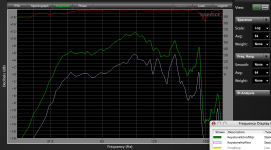
Looking at the overlay picture in Post #1771 again, there is actually no decrease in the LF corner frequency whatsoever using a second cabinet.
The overall forward gain has increased by the same amount, about 1 dB as it does with the second cabinet along side, undriven and shorted.
In the screen shot below, the green trace is a single cabinet output, using a 28 Hz BW24 HP and a 100 Hz LP, the same filters are used for all three traces with the same drive level.
The blue trace shows two of the same cabinets side by side, the second speaker shorted out (a wire between the + and - terminals), so the additional cabinet is just a "dummy", increasing frontal area.
The increased frontal area adds about 1 dB gain overall.
The lavender trace shows the addition of the second cabinet with the speaker not shorted. The addition of the second cabinet in this case increases the 40-45 Hz area, then causes a sharp dip, followed by more rising response, and another dip.
I found the difference the second un-powered cabinet made to the response curves rather interesting.
Art Welter
Attachments
Last edited:
Looking at the overlay picture in Post #1771 again, there is actually no decrease in the LF corner frequency whatsoever using a second cabinet.
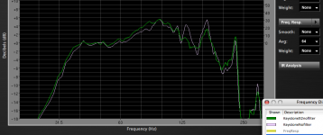
Hi Art,
The multiple speaker (green) trace does however pass through the -1dB point at a lower frequency than the single speaker (white) trace.
Kind regards,
David
Hello David,
About Export. when prinnting out horn data I guess "Side length" is for cutting a template for a square horn. In other words it is width with stretch factor added.
If I have understood everything right there will be no problem when doing a square horn but if it is for rectaungular there are no data for top/ bottom. Anything you can add?
Lars
I've done data outputs for rectangular horns where one pair of sides are the conical expansion onto which the curved sides are laid . The last data column there represents the length from throat to mouth measured along the wood of the conical pieces, ie. it is the axis measurement expanded by 1/cos(theta) where 'theta' is the half-angle of the conical expansion .
Hope this helps
Mark
- Home
- Loudspeakers
- Subwoofers
- Hornresp