Would it be reasonably possible to provide for two different tapped horn models, similar to the current two different horn models: front loaded horn and offset horn? I have found from running quite a number of tapped horn models that many models do benefit from minimizing L12, ideally the driver would energize the horn at S1 instead of S2, you might call this the front loaded tapped horn, versus entering the horn path at S2 for your current offset tapped horn. In the bargain you would gain an additional section for modeling this type of tapped horn, making the program even more versatile.
Hi Oliver,
Unfortunately, the enhancements you are seeking would require a lot of work - something I am not in a position to do at this time. Setting L12 = 0.10 cm in the current tapped horn model should however achieve effectively the same result - although granted, an additional segment does not become available.
It could be an interesting exercise to build your suggested model in AkAbak and then compare the results with the Hornresp L12 = 0.10 approximation to see if the differences are of practical significance.
In the meantime, please keep a lookout for any bugs...
") .
.Kind regards,
David
Last edited:
It sure does. Sampling it 533 times however becomes a little more workAnd here's me thinking that the Sample tool already provided "more than sufficient" information
I would be fine with it just automatically sampled the tool at all frequencies the normal export function does and dump it into a file with similar structure.
It's usefulness may not be known until it is implemented.From a practical viewpoint I wonder just how useful such additional data might be - it seems that there is enough confusion out there already, when it comes to interpreting the Hornresp Maximum SPL chart
If a "script" is made for the sample tool it's behavior would carry over to all graphs it samples.
A current limit (or current shown in sample tool) might be useful as is relates to a limit imposed by VC wire area or cable area. Or max amp current if you want. Due to phase it might be hard to calculate from the power given.
As Rg loss is ignored when power is shown I guess it is best to leave it "out"(in) here as well. So voltage at the VC. Can't hurt to do both though.By 'drive voltage' do you mean Eg, or the voltage at the voice-coil taking into account Rg losses?
I guess phase is the same as the electrical phase already exported, so it might not be necessary.By 'phase' I assume you mean the phase difference between voltage and current?
This is an advanced feature not used very often so optimization on speed is not a priority.
On any normal computer today it should not be a problem though.
Keep it in mind and see what happens. Only you knows the coding involved and how it might be solved, and if it's worth the time compared to other things.
It could be an interesting exercise to build your suggested model in AkAbak and then compare the results with the Hornresp L12 = 0.10 approximation to see if the differences are of practical significance.
Hi Oliver,
I couldn't resist checking for myself
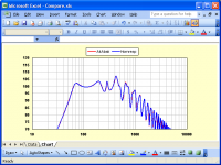
.The attached Excel chart compares the AkAbak result for a tapped horn having the first diaphragm side facing axially into the throat at S1, against the standard Hornresp result for the same tapped horn, but with L12 = 0.10 cm and S1 = S2.
As expected, the results are essentially identical.
Kind regards,
David
Attachments
Only you knows the coding involved and how it might be solved, and if it's worth the time compared to other things.
Hi David_Web,
Thanks for your comments.
I will have a look when I get a chance - I'm not promising anything, though
.Kind regards,
David
i have a question about the le input in hr.
in ts parameterrs the value usualy is given @ 1khz and sometimes also @ 10 khx
i always thought that the le value was a static nr,but recently i discoverd that the value decreases with increasing frequenty.
this pic is from a typical beyma woofer ,le =2.4 @ 1khz as given in
th small parameters
when moddeling a subwoofer in the range of 30hz > 120 hz ,shouldnt the le vallue be according to the le vallue in that freq band?
reason for asking is sometimes inserting (adding coil) a higher le value gives a smoother responce in the pasband.
in ts parameterrs the value usualy is given @ 1khz and sometimes also @ 10 khx
i always thought that the le value was a static nr,but recently i discoverd that the value decreases with increasing frequenty.
this pic is from a typical beyma woofer ,le =2.4 @ 1khz as given in
th small parameters
An externally hosted image should be here but it was not working when we last tested it.
when moddeling a subwoofer in the range of 30hz > 120 hz ,shouldnt the le vallue be according to the le vallue in that freq band?
reason for asking is sometimes inserting (adding coil) a higher le value gives a smoother responce in the pasband.
Hi epa,
The Hornresp simulation model assumes a perfect inductor, where the value of the inductance is independent of frequency. The reactance of that inductance will however increase with frequency:
Reactance (ohms) = 2 * Pi * frequency (hertz) * inductance (henrys)
Yes, as far as specifying just the inductance of the driver voice-coil is concerned.
The value of an external inductor can be added to the driver voice-coil value if so desired, to modify the overall system response:
Le = L external + L voicecoil
Kind regards,
David
i have a question about the le input in hr. in ts parameterrs the value usualy is given @ 1khz and sometimes also @ 10 khx i always thought that the le value was a static nr,but recently i discoverd that the value decreases with increasing frequenty.
The Hornresp simulation model assumes a perfect inductor, where the value of the inductance is independent of frequency. The reactance of that inductance will however increase with frequency:
Reactance (ohms) = 2 * Pi * frequency (hertz) * inductance (henrys)
when moddeling a subwoofer in the range of 30hz > 120 hz ,shouldnt the le vallue be according to the le vallue in that freq band?
Yes, as far as specifying just the inductance of the driver voice-coil is concerned.
reason for asking is sometimes inserting (adding coil) a higher le value gives a smoother responce in the pasband.
The value of an external inductor can be added to the driver voice-coil value if so desired, to modify the overall system response:
Le = L external + L voicecoil
Kind regards,
David
I will have a look when I get a chance.
Hi David_Web,
Values for the following parameters have been now been added to the standard exported chart data list.
They are included even when the Maximum SPL tool is not used.
Ein - Loudspeaker system input voltage
Pin - Loudspeaker system input power
Iin - Loudspeaker system input current
IPhase - Phase difference between Iin and Ein
Product Number 2830-110214 refers.
Kind regards,
David
The value of an external inductor can be added to the driver voice-coil value if so desired, to modify the overall system response.
I should have perhaps added that the external inductor will act simply as a low-pass filter
.tnx again david.I should have perhaps added that the external inductor will act simply as a low-pass filter
i know its a passive component,but in use of a sub its not much an isu.
when i look at most graps of inductance,i see that for a sub the le value @100 hz is ~(near enough)double that of 1 khz .
so i double the le value (i.e.0.9mh >1,8mh)in hr when modeling a sub 30>100 hz.
is this assumption about wright?
when i look at most graps of inductance,i see that for a sub the le value @100 hz is ~(near enough)double that of 1 khz . so i double the le value (i.e.0.9mh >1,8mh)in hr when modeling a sub 30>100 hz. is this assumption about wright?
Hi epa,
It seems like a reasonable thing to do, but I don't really know for sure
.Others with more practical experience in these matters would be in a better position to comment.
Obviously though - the closer the theoretical value of Le is to the actual value over the frequency range of interest, the more accurate the predictions are likely to be.
You might like to try varying the value of Le using the Hornresp Loudspeaker Wizard to see how much the results change. You may find that for your proposed system, at sub-woofer frequencies, the differences are not that great anyway
.Kind regards,
David
Last edited:
Multiple enclosure coupling applies to rear vented tuning, is this accurate?
Hi Dan,
As far as I know, the simulation model should be okay. I haven't seen any comparisons of predicted versus measured results for such systems, so I am not in a position to comment on accuracy.
Kind regards,
David
Hello,
May I suggest that the value of the source resistor (Rg) doesn't have the same influence on the equivalent Qe in the case of a single loudspeaker than in the case of multiple loudspeakers.
Qe = Qes . ((Re + Rg)/Re)
and then on the equivalent Qts.
As the resonance frequency is given by:
Fb(Hz)=Ka*Fs/Qts
A variation in the Qts will induce a variation in Fb.
(In the case the source resitor is Rg = 0 then there should not be any difference...)
Best regards from Paris, France
Jean-Michel Le Cléac'h
Multiple enclosure coupling applies to rear vented tuning, is this accurate?
When simulating mulitples of a rear vented alignment, HR significantly lowers tuning of the total system.
Just throwing this out for discussion:
Is there a possibility that as in the case of multiple horns exhibiting different behavior due to mutual coupling there are multiple vents coupling?
In a single enclosure that can be the case when you have a multitude of vents. Rarely does the calculated length work when there are four vents on the same baffle plane. When there are multiple vents to achieve low vent velocity and the diameter is small due to baffle restrictions....
If I were stripping windows down to only what was required to run Hornresp what would I need?
Hi Dan,
Sorry, but I have no idea on that one
.Kind regards,
David
Hi David,
If I were stripping windows down to only what was required to run Hornresp what would I need?
hr is a standalone program ,doesnt need regestry settings.
you need an xp lite version, nothing fancy.
if you were running mac os use a virtual machine?
Hi epa,
I am attempting to get it running on my MBP under WineBottler, I normally run a full XP VM under Fusion but I am considering an instance of XP via bootcamp for a measurement platform. This being my first attempt with a Wine based VM I am feeling around in the dark, hence the question on dependencies.
I am attempting to get it running on my MBP under WineBottler, I normally run a full XP VM under Fusion but I am considering an instance of XP via bootcamp for a measurement platform. This being my first attempt with a Wine based VM I am feeling around in the dark, hence the question on dependencies.
- Home
- Loudspeakers
- Subwoofers
- Hornresp