Hi, first of many thanks to David, for making this amazingly powerful program, which I am only beginning to understand.
I originally just downloaded it, because all the Tapped Horn designs in the Subwoofer section had HornResp parameters included, so it was an easy way for me to vary the input power into their designs and see how they simmed. However, after reading some tutorials, and getting to know the programm a bit better, I realized that it was capable of so much more than (Tapped) Horns, and I'm slowly beginning to replace WinISD with HornResp for closed and vented boxes.
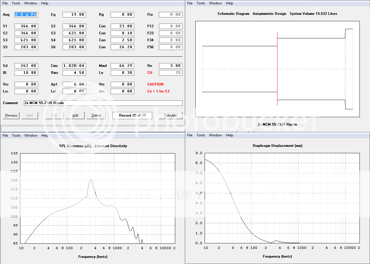
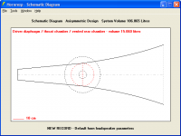
Anyways, what I'm trying to do, is simulate a Linkwitz style Dipole Woofer, and I'm not sure if I'm entering my parameters correctly. Can somebody take a quick look at my Parameters vs. my Schematic, and tell me if I'm going in the right direction with this.
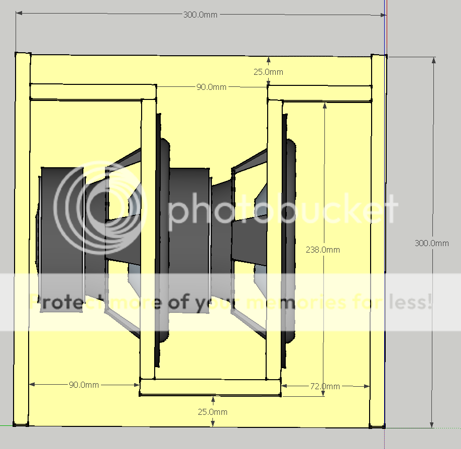
The bend on the far right is supposed to represent the 25mm where the side walls of the enclosure continue, but the dividers are gone. Ideally I would have wanted to make a similar section on the left side, but there's no option to add two segments behind the woofer. I'm not sure how important these sections are though, ie how much effect they'd have on the sim. Edit: I resimmed without the right expansion section, instead making L12 2.5cm longer, and the only changes were some minor differences outside of passband (intended xover around 80~100Hz).
The other thing I'm unsure of is how long I should simulate L12 & L56 as. I used the distance from the back wall to the front wall (ie 238mm) However, perhaps I should be measuring from the center of the driver to the opening, which would be only about half that length. Hope somebody more knowledgeable about these kind of sims can shed some light. Edit2: changing this to 14cm doesn't change too much below 100Hz (even shorter and you start to lose output in the bass region). So is it safe to conclude that this simply doesn't matter?
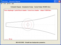
Also, I have a further question. The Woofer I'm using is a Dual Voicecoil (DVC) design, so I simply used Re/2 and Le/2 to indicate a parallel connection of the voicecoils. Obviously Sd is invariant, regardless of how the coils are wired. However I'm a bit unsure about the other 4 parameters (Cms, Mmd, Bl, Rms), especially considering Bl apparently has something to do with the voice coil length. Do I need to change any of those as well?
Thanks in advance for the guidance!
I originally just downloaded it, because all the Tapped Horn designs in the Subwoofer section had HornResp parameters included, so it was an easy way for me to vary the input power into their designs and see how they simmed. However, after reading some tutorials, and getting to know the programm a bit better, I realized that it was capable of so much more than (Tapped) Horns, and I'm slowly beginning to replace WinISD with HornResp for closed and vented boxes.
Anyways, what I'm trying to do, is simulate a Linkwitz style Dipole Woofer, and I'm not sure if I'm entering my parameters correctly. Can somebody take a quick look at my Parameters vs. my Schematic, and tell me if I'm going in the right direction with this.
The bend on the far right is supposed to represent the 25mm where the side walls of the enclosure continue, but the dividers are gone. Ideally I would have wanted to make a similar section on the left side, but there's no option to add two segments behind the woofer. I'm not sure how important these sections are though, ie how much effect they'd have on the sim. Edit: I resimmed without the right expansion section, instead making L12 2.5cm longer, and the only changes were some minor differences outside of passband (intended xover around 80~100Hz).
The other thing I'm unsure of is how long I should simulate L12 & L56 as. I used the distance from the back wall to the front wall (ie 238mm) However, perhaps I should be measuring from the center of the driver to the opening, which would be only about half that length. Hope somebody more knowledgeable about these kind of sims can shed some light. Edit2: changing this to 14cm doesn't change too much below 100Hz (even shorter and you start to lose output in the bass region). So is it safe to conclude that this simply doesn't matter?
Also, I have a further question. The Woofer I'm using is a Dual Voicecoil (DVC) design, so I simply used Re/2 and Le/2 to indicate a parallel connection of the voicecoils. Obviously Sd is invariant, regardless of how the coils are wired. However I'm a bit unsure about the other 4 parameters (Cms, Mmd, Bl, Rms), especially considering Bl apparently has something to do with the voice coil length. Do I need to change any of those as well?
Thanks in advance for the guidance!
Last edited:
...Hi, first of many thanks to David, for making this amazingly powerful program, which I am only beginning to understand...
Hi, FYI: Just a test and a template to be copied:
b
")
Attachments
PPSL
PPSL in Hornresp
Hi David,
I'm trying to model a PPSL, e.g.:
http://www.diyaudio.com/forums/subwoofers/176729-klipsch-horn-woofer-designs-3.html.
Obviously, I could just model it as a BR, but that does not account for the front chamber (plenum). The OD horn looks like it may be the better choice, but when I read the help file I get the impression, that the rear chamber vent may be returned into the horn at the horn throat, which I guess would be S1.
It is nice to be able to model the front chamber of the PPSL as an OD (driver entry point at S2), and it would be great if the rear could be vented like a BR, or-even better-like a CH using the fourth horn section.
Regards,
Attachments
The OD horn looks like it may be the better choice, but when I read the help file I get the impression, that the rear chamber vent may be returned into the horn at the horn throat, which I guess would be S1.
Hi Oliver,
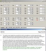
I'm not sure that I understand the PPSL design correctly, but in an attempt to clarify the Hornresp OD horn options:
1. Add a new record using the default record as the parent.
2. Double-click Nd to select OD.
3. Double-click Fr to select Ap and note the message in the status bar panel at the bottom of the input screen - Ap and Lpt specify the port tube in a vented rear chamber. See also the red description in the first screenprint attached (Ap.png).
4. Double-click Ap to select Ap1 and note the message in the status bar panel at the bottom of the input screen - Ap1 and Lpt specify the port opening between a throat chamber and the entry into the horn at S2. See also the red description in the second screenprint attached (Ap1.png).
In other words, Ap is not the same as Ap1
.Hope this helps.
Kind regards,
David
Attachments
PPSL and Rear Chamber Vent
Hi David,
Thank you for the explanation. Looks like I got it correct to begin with, I just didn't want to pass along information while I still had questions.
I had not noted the difference between Ap and Ap1. That adds another option, nice.
Thanks again, Regards,
Hi David,
Thank you for the explanation. Looks like I got it correct to begin with, I just didn't want to pass along information while I still had questions.
I had not noted the difference between Ap and Ap1. That adds another option, nice.
Thanks again, Regards,
Hi, FYI: Just a test and a template to be copied:
b
Hi, thanks for the help, also thanks for correcting my Sd, not sure where I picked up the wrong value.
I played around, and no matter how big or small I make the baffle, also when I compare your method of modelling to mine, the simulation below 100Hz seems to remain exactly the same.
Perhaps I'd need Edge to simulate this properly, or does it really not make a difference at all? I can hardly believe that....
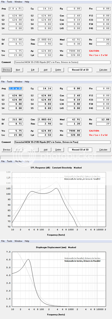
What however does make a huge difference (unless I'm modeling this wrong), which surprised me, is switching from series-parallel to parallel-series connection (using two dual voice coil drivers). Is this really such a huge change due to the different inductance of the different wiring configurations? I would have thought it would give 0 net change (as the total inductance seen by the amp remains the same), but perhaps I would have thought wrong?
Would the other parameters perhaps somehow measure thus differently when measured with the voicecoils in series, that the simulation would end up exactly the same again?
Last edited:
Just input the single driver specs using the voice coils as measured, and select series/parallel in HR. If you want to use a different voice coil setup, you will have to adjust the other parameters. More than Re and Le are altered when making this switch.
Thanks, I figured as much.
So that begs the question - would the two options simulate the exact same? Or would there really be differnces (though not as big as my incorrect simulation would indicate)?
Thanks, I figured as much.
So that begs the question - would the two options simulate the exact same? Or would there really be differnces (though not as big as my incorrect simulation would indicate)?
----------------------------
Hi James,
Answer for the question above: Yes, but levels/load would of course be different if not also changing the wiring:
See my new comparison that only uses different coil hook ups but not changing the wirings as should be done to be correct.
post# 1466:
I played around, and no matter how big or small I make the baffle, also when I compare your method of modelling to mine, the simulation below 100Hz seems to remain exactly the same.
The reason why you get the same response is you are only modeling the drivers into IB, i.e. the rear of the drivers are terminated into an infinite(closed) volume. To sum both rear and front contributions: you must after pressing the 'Calculate' button and choose 'SPL' response also click on the 'Tools' menu and press the 'Combined' response and enter the path difference, too.
Perhaps I'd need Edge to simulate this properly, or does it really not make a difference at all? I can hardly believe that....
The 'Edge' program cannot model your enclosure including the specific drivers in use.
What however does make a huge difference (unless I'm modeling this wrong), which surprised me, is switching from series-parallel to parallel-series connection (using two dual voice coil drivers). Is this really such a huge change due to the different inductance of the different wiring configurations? I would have thought it would give 0 net change (as the total inductance seen by the amp remains the same), but perhaps I would have thought wrong?..Would the other parameters perhaps somehow measure thus differently when measured with the voicecoils in series, that the simulation would end up exactly the same again?..
There should be no difference(but the relative levels) when if 'switching from series-parallel to parallel-series connection' but a small difference in the entered TS parameters due to program round up effects.
To change from paralleled coils to series connected:
Click Sd and save the information of the calculated primary TS parameters, then double the BL value , Le and Re should also be quadrupled.
Click on Cms and enter the saved Vas value:
Click on Rms and enter saved fs and Qms.
Last:Check Mmd by entering fs again.
Compare the saved primary TS parameters by clicking on the Sd again,there should be no difference.
Note: In reality when using measured series/parallel connected coils:
All parameters are slightly off the theoretical as used here above, but if used, should return almost identical plotted graphs in HR,only very small (benign)deviations should be presented.
b
PS: If you seriously really believe in this type of enclosure for use as sub enclosures:
I urge you to invest in MJK:s programs that would model this type of enclosures at another more useful level by including room effects, active/passive filters and enclosure damping and so on...and complement the outcome from HR with the features not found in MJK:s program.
Attachments
Thanks, I've been planning to get the MJK sheets for some time ($25 is not really the issue), however obtaining a MathCad program has thus far hindered me. But that's not really for this thread I guess.
One more thing though: You are of course right, running in Series-Series-configuration will give a 6dB level shift vs Series-Parallel. But that wasn't quite what I was talking about. I was talking about using a Parallel-Series-configuration instead of Series-Parallel. ie keeping the net impedance at 8Ω, and not bumping it up to 32Ω. ie. on the right image it should read Nd: 2P.
I take it in that case the output must be identical then, if I'm now finally simming correctly.
For what it's worth, I'm not really considering pursuing the ripole style option with these drivers, but I was thinking, depending on how they sim, no harm in building a cheap mdf/particle board test cab.
Last edited:
Hornresp Version 28.10
Hi Everyone,
Hornresp Version 28.10 has just been released.
The following changes have been made to the Loudspeaker Wizard:
1. Four Segment Tapped Horn Loudspeaker Wizard:
Horn parameter sliders are now displayed in two views:
'Horn S1 - S5' shows S1, S3, S5 and L12, L23, L34, L45
'Horn S2 - S4' shows S2, S3, S4 and L12, L23, L34, L45
Under default conditions S1, S2, S3, S4 and S5 can be adjusted independently.
Double-clicking the S2 slider label in view 'Horn S2 - S4' combines segments 1 and 2 and automates the calculation of S2. Slider S2 is disabled. Double-clicking again re-enables slider S2 and de-combines segments 1 and 2.
Double-clicking the S4 slider label in view 'Horn S2 - S4' combines segments 3 and 4 and automates the calculation of S4. Slider S4 is disabled. Double-clicking again re-enables slider S4 and de-combines segments 3 and 4.
As with the previous version, double-clicking any length slider changes the flare type for that segment.
2. Three Segment Tapped Horn Loudspeaker Wizard:
Horn parameter sliders are displayed in a single view:
'Horn S1 - S4' shows S1, S2, S3, S4 and L12, L23, L34
Under default conditions S1, S2, S3 and S4 can be adjusted independently.
Double-clicking the S2 slider label in view 'Horn S1 - S4' combines segments 1 and 2 and automates the calculation of S2. Slider S2 is disabled. Double-clicking again re-enables slider S2 and de-combines segments 1 and 2.
Double-clicking the S3 slider label in view 'Horn S1 - S4' combines segments 2 and 3 and automates the calculation of S3. Slider S3 is disabled. Double-clicking again re-enables slider S3 and de-combines segments 2 and 3.
Double-clicking both the S2 and S3 slider labels in view 'Horn S1 - S4' combines segments 1 , 2 and 3 and automates the calculation of S2 and S3.
As with the previous version, double-clicking any length slider changes the flare type for that segment.
3. Offset Driver Horn Loudspeaker Wizard:
Under default conditions S1, S2 and S3 can be adjusted independently.
Double-clicking the S2 slider label combines segments 1 and 2 and automates the calculation of S2. Slider S2 is disabled. Double-clicking again re-enables slider S2 and de-combines segments 1 and 2.
As with the previous version, double-clicking any length slider changes the flare type for that segment.
My thanks to Oliver (tb46) for prompting me to implement the above changes.
As always, could you please report any bugs you find, no matter how minor they may seem.
Kind regards,
David
Hi Everyone,
Hornresp Version 28.10 has just been released.
The following changes have been made to the Loudspeaker Wizard:
1. Four Segment Tapped Horn Loudspeaker Wizard:
Horn parameter sliders are now displayed in two views:
'Horn S1 - S5' shows S1, S3, S5 and L12, L23, L34, L45
'Horn S2 - S4' shows S2, S3, S4 and L12, L23, L34, L45
Under default conditions S1, S2, S3, S4 and S5 can be adjusted independently.
Double-clicking the S2 slider label in view 'Horn S2 - S4' combines segments 1 and 2 and automates the calculation of S2. Slider S2 is disabled. Double-clicking again re-enables slider S2 and de-combines segments 1 and 2.
Double-clicking the S4 slider label in view 'Horn S2 - S4' combines segments 3 and 4 and automates the calculation of S4. Slider S4 is disabled. Double-clicking again re-enables slider S4 and de-combines segments 3 and 4.
As with the previous version, double-clicking any length slider changes the flare type for that segment.
2. Three Segment Tapped Horn Loudspeaker Wizard:
Horn parameter sliders are displayed in a single view:
'Horn S1 - S4' shows S1, S2, S3, S4 and L12, L23, L34
Under default conditions S1, S2, S3 and S4 can be adjusted independently.
Double-clicking the S2 slider label in view 'Horn S1 - S4' combines segments 1 and 2 and automates the calculation of S2. Slider S2 is disabled. Double-clicking again re-enables slider S2 and de-combines segments 1 and 2.
Double-clicking the S3 slider label in view 'Horn S1 - S4' combines segments 2 and 3 and automates the calculation of S3. Slider S3 is disabled. Double-clicking again re-enables slider S3 and de-combines segments 2 and 3.
Double-clicking both the S2 and S3 slider labels in view 'Horn S1 - S4' combines segments 1 , 2 and 3 and automates the calculation of S2 and S3.
As with the previous version, double-clicking any length slider changes the flare type for that segment.
3. Offset Driver Horn Loudspeaker Wizard:
Under default conditions S1, S2 and S3 can be adjusted independently.
Double-clicking the S2 slider label combines segments 1 and 2 and automates the calculation of S2. Slider S2 is disabled. Double-clicking again re-enables slider S2 and de-combines segments 1 and 2.
As with the previous version, double-clicking any length slider changes the flare type for that segment.
My thanks to Oliver (tb46) for prompting me to implement the above changes
.As always, could you please report any bugs you find, no matter how minor they may seem.
Kind regards,
David
Neat!
However could you bring back previous behavior when it comes to scaling the sliders?
As the highest value set the range appropriate range for the rest of the sliders. I thought it was easier to use.
Although I guess more people should state there preference.
The message "double-click x for auto" seems to be a bit random when adjusting the slider. Should probably only show up when mouse over S1 to S5 label.
Same with "double-click x for flare". As both obscure the total length message.
Changing any slider also changes S3 value label (if S3 was the last slider changed). Only happens once though.
Hi David,
Thanks for making all cross-sectional areas adjustable independently in the Wizards. The Auto features will take some getting used to, but I like them. I have not had a lot of time to use all the new features, but I'll let you know if I run into any problems.
Thanks again for your continuing effort,
Regards,
Possible Version Incompatibility
Hi David,
I imported the attached tHdual4.txt and found some incompatibility between it and the newest Hornresp version:
1. Open Wizard, set to: Response / Horn S1 - S4 / L23 Variable
2. Move S3, then move it back to the initial value (i.e.: 199.00 intead of 199.63)
3. Click anywhere on the S4 slider or slider bar, and the value of S3 jumps, but stays stable after that (further clicking of S4 will not affect it).
This behaviour does not occur with my own old 3 section TH files (created over the last few years, at least I haven't found one yet). I asked the originator of that file for the version number, Post #12:
http://www.diyaudio.com/forums/subw...e-comment-my-hornresp-simulations-mcm8-2.html
Regards,
Attachments
Thanks very much again David.
Hi jamikl,
You're welcome
.Kind regards,
David
Hi David_Web,
Thanks for the feedback.
The tapped horn wizard area slider scaling arrangements were altered because a number of users felt that the original method was somewhat confusing, with the slider control settings moving around for no apparent reason, even though the actual slider values did not change.
All loudspeaker types now use the same scaling system (previously the tapped horn wizard was different to the others). An advantage of the new method is that tapped horn areas are no longer restricted to 64000 sq cm (although this limitation does not really present a problem in practice).
I would be very interested in receiving more feedback on this issue - do other users have a preference for the old scaling method?
The "double-click" messages are definitely not random. They occur when those sliders that can be double-clicked, get the focus. The total length message re-appears just as soon as a slider value is altered. I included the feature so that users could not fail to see the messages - rather than relying on the mouse being moved over a label for the information to be displayed.
I do agree however that the method employed is a bit intrusive, and may be distracting for some users. Accordingly the "double-click x for flare" messages are no longer displayed - this information is already contained in the Loudspeaker Wizard section of the Help file anyway. The "double-click x for auto" message is now only shown the first time that the slider gets the focus, not every time (it was easier to do this than to detail all the different options in the Help file).
This problem has been fixed in the latest release. Product Number 2810-101201 refers.
Kind regards,
David
Thanks for the feedback.
However could you bring back previous behavior when it comes to scaling the sliders? As the highest value set the range appropriate range for the rest of the sliders. I thought it was easier to use. Although I guess more people should state there preference.
The tapped horn wizard area slider scaling arrangements were altered because a number of users felt that the original method was somewhat confusing, with the slider control settings moving around for no apparent reason, even though the actual slider values did not change
.All loudspeaker types now use the same scaling system (previously the tapped horn wizard was different to the others). An advantage of the new method is that tapped horn areas are no longer restricted to 64000 sq cm (although this limitation does not really present a problem in practice).
I would be very interested in receiving more feedback on this issue - do other users have a preference for the old scaling method?
The message "double-click x for auto" seems to be a bit random when adjusting the slider. Should probably only show up when mouse over S1 to S5 label. Same with "double-click x for flare". As both obscure the total length message.
The "double-click" messages are definitely not random
. They occur when those sliders that can be double-clicked, get the focus. The total length message re-appears just as soon as a slider value is altered. I included the feature so that users could not fail to see the messages - rather than relying on the mouse being moved over a label for the information to be displayed.I do agree however that the method employed is a bit intrusive, and may be distracting for some users. Accordingly the "double-click x for flare" messages are no longer displayed - this information is already contained in the Loudspeaker Wizard section of the Help file anyway. The "double-click x for auto" message is now only shown the first time that the slider gets the focus, not every time (it was easier to do this than to detail all the different options in the Help file).
Changing any slider also changes S3 value label (if S3 was the last slider changed). Only happens once though.
This problem has been fixed in the latest release. Product Number 2810-101201 refers.
Kind regards,
David
I have now seen the same behaviour as pointed out in the last post with some of my old TH models, so it looks like a bug. I cannot make it happen every time, or consistently?
Hi Oliver,
Many thanks for the detailed description of the problem. The bug has now been fixed. The latest release is Product Number 2810-101201.
I looked into the possibility of locking individual input parameter values, but decided not to proceed with the implementation of this feature. I think it might have created more new problems than it would have solved
.Kind regards,
David
- Home
- Loudspeakers
- Subwoofers
- Hornresp