In addition to what David said: When dealing with very compact vented designs, boundary effects of the "reflex tunnel" always have to be taken into account which no simulation package so far is able to simulate to 100%. The placing of the port and the numer of adjancing walls (of the enclosure) at the port is changing the port resonance slightly, the distance between the back wall of the enclosure and the port end does, too. To see exactly what happens here one has to build up a prototype, even akabak won´t take this into account correctly.Hi David
When using Hornresp to simulate a horn with a vented rear chamber, does the port length include any end correction?
Ian
In addition to what David said: When dealing with very compact vented designs, boundary effects of the "reflex tunnel" always have to be taken into account which no simulation package so far is able to simulate to 100%. The placing of the port and the numer of adjancing walls (of the enclosure) at the port is changing the port resonance slightly, the distance between the back wall of the enclosure and the port end does, too. To see exactly what happens here one has to build up a prototype, even akabak won´t take this into account correctly.
I'm aware of all that and will adjust after building, I just needed to know to make sure there's enough room for the maximum likely length of port.
Ian
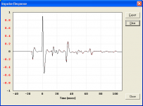
There seems to still be something minor amiss with the impulse response tool, even though it is very much improved. Please, see attached impulse response comparison, same simulation as before, Lpt changed from 1.78 to 1.79cm.
Hi Oliver,
I have found a way of preventing the anomaly in the impulse response for your Lpt = 1.79 cm test example, but I would like to check with Jean-Michel to see if he is happy with the method I am using before releasing any update to Hornresp. Hopefully this can be done early next week.
The attached screenprint compares the impulse response results for your tapped horn example with Lpt = 1.79 cm (black trace) and Lpt = 1.78 cm (red trace). You can see that the difference is now minimal, as it should be.
Kind regards,
David
Attachments
Hello Oliver,
There is 2 points in your question:
High frequency resonances due to the throat chamber depth induce rapid variations of the phase and therefore to large amplitude peaks and dips of the group delay curve (at HF)
Now, when one wants to perform minute changes in the front chamber the resonance frequencies are more or less far from the discrete frequencies used by Hornresp. This explains why the height of peaks or dips on the group delay curve becomes larger sometimes.
Then, as the Impulse Response module of Hornresp uses the mean group delay at high frequency as an internal parameter, in some cases the mean HF group delay may be noticeably larger or smaller than when the depth is a bit larger or smaller (because the resonance frequencies don't coincide anymore with the discrete frequencies used in Hornresp) .
One solution I found and which is currently under test is to use the median value of the group delay between 10kHz and 20kHz in place of the mean value.
The negative time impulses are due to the fact that we choose to use as a time reference for the spectrogram -as it is usual- the time at which the energy of the spectrogram is the largest inside a very large of frequency.
This peak of high energy (having also a large HF content) is normally related to the wave emitted by the front of the loudspeaker (that's why the upward front of the corresponding pulse ).
Now in TH, depending on the paths of the front wave and the rear wave, a wave emitted by the rear of the loudspeaker (and having a "downward" front pulse) may arrive before the "front wave" and therefore that lower energy pulse will be seen as having a negative time relatively to the main pulse taken as a reference. This is probably counterintuitive but it is also very convenient for the operation of the automatic scaling module I wrote for Hornresp.
To conclude, this is not related to the shape of the Fourier window (raised cosine having a frequency dependant width) . (Please note that the Impulse Reponse calculation in Hornresp is not based on an inverse FFT but is a proprietary algorithm of mine adapted to a discrete frequencies problem...)
Best regards from Paris, France
Jean-Michel Le Cléac'h
There is 2 points in your question:
I have seen similar simulation artifacts with changes of the Vtc in tapped horn simulations using a throat chamber...
High frequency resonances due to the throat chamber depth induce rapid variations of the phase and therefore to large amplitude peaks and dips of the group delay curve (at HF)
Now, when one wants to perform minute changes in the front chamber the resonance frequencies are more or less far from the discrete frequencies used by Hornresp. This explains why the height of peaks or dips on the group delay curve becomes larger sometimes.
Then, as the Impulse Response module of Hornresp uses the mean group delay at high frequency as an internal parameter, in some cases the mean HF group delay may be noticeably larger or smaller than when the depth is a bit larger or smaller (because the resonance frequencies don't coincide anymore with the discrete frequencies used in Hornresp) .
One solution I found and which is currently under test is to use the median value of the group delay between 10kHz and 20kHz in place of the mean value.
It would be great if you or Jean-Michel could shed a little light on the nature of the negative time impulse response stemming from the Fourier transform of the SPL response.
The negative time impulses are due to the fact that we choose to use as a time reference for the spectrogram -as it is usual- the time at which the energy of the spectrogram is the largest inside a very large of frequency.
This peak of high energy (having also a large HF content) is normally related to the wave emitted by the front of the loudspeaker (that's why the upward front of the corresponding pulse ).
Now in TH, depending on the paths of the front wave and the rear wave, a wave emitted by the rear of the loudspeaker (and having a "downward" front pulse) may arrive before the "front wave" and therefore that lower energy pulse will be seen as having a negative time relatively to the main pulse taken as a reference. This is probably counterintuitive but it is also very convenient for the operation of the automatic scaling module I wrote for Hornresp.
To conclude, this is not related to the shape of the Fourier window (raised cosine having a frequency dependant width) . (Please note that the Impulse Reponse calculation in Hornresp is not based on an inverse FFT but is a proprietary algorithm of mine adapted to a discrete frequencies problem...)
Best regards from Paris, France
Jean-Michel Le Cléac'h
Last edited:
Regarding Hornresp it might be of some interest to point to a simulation of an H-baffle OB with the help of the programme which I posted in the AudioCircle: 15" woofer at 1KHz? .
/Erling
/Erling
Last edited:
Regarding Hornresp it might be of some interest to point to a simulation of an H-baffle OB with the help of the programme which I posted in the AudioCircle.
Hi Erling,
Thanks for this link.
It never ceases to amaze me - the variety of designs that users simulate in Hornresp
") .
.Kind regards,
David
When I try to change power and Xmax in max SPL tool it still takes the previously saved value. So now you have to save the new value every time you want to use it with a different value.
Hi David_Web,
Thanks for this. I must have inadvertently introduced the bug when I added the functionality to permanently save Pmax and Xmax values as part of the data record, in Version 26.50
.I will let everyone know when the problem is fixed.
Kind regards,
David
Hornresp Version 28.00
Hi Everyone,
Hornresp Version 28.00 has just been released. Parabolic horns can now be modelled. Amongst other things, this enables horn segments having two parallel walls and two tapered walls to be more accurately simulated.
My thanks to Bjørn (Kolbrek) for supplying the necessary formulas to calculate the throat acoustical impedance of a finite parabolic horn.
The inclusion of the parabolic horn option required significant changes to the program - could you please let me know if you find any bugs.
Kind regards,
David
- Home
- Loudspeakers
- Subwoofers
- Hornresp