I absolutely love this program but there is one thing that has extremely frusterated me many times. If a design is not saved and the Esc key is hit, POOF!!! your design is gone. I have have spent an hour working an a design many a time and then accidentally done this thinking Autocad or some other program was the highlighted screen and lost all my hard work!
Posts #954/#955/#958 Ap1_Throat Chamber Exit Area
Hi David,
I think I may be getting it now -") : Ap1=0 is basically treated as an invalid input, the port is opened, Ap1 is set to equal Atc in the schematic, and Lpt disabled. Once Ap1=>0.1 the inputs are accepted and applied to the calculations. I assume that "No provision is made for horn transmission losses" also applies to the throat chamber and port.
: Ap1=0 is basically treated as an invalid input, the port is opened, Ap1 is set to equal Atc in the schematic, and Lpt disabled. Once Ap1=>0.1 the inputs are accepted and applied to the calculations. I assume that "No provision is made for horn transmission losses" also applies to the throat chamber and port.
What all this means - in reality, at different power levels - can only be determined by building and measuring. Maybe transferring to AkAbak, and adding losses may get me closer.
Thanks again for the help, and a great program. Your constant stream of updates and advice is greatly appreciated.
Regards.
Hi David,
I think I may be getting it now -
: Ap1=0 is basically treated as an invalid input, the port is opened, Ap1 is set to equal Atc in the schematic, and Lpt disabled. Once Ap1=>0.1 the inputs are accepted and applied to the calculations. I assume that "No provision is made for horn transmission losses" also applies to the throat chamber and port.What all this means - in reality, at different power levels - can only be determined by building and measuring. Maybe transferring to AkAbak, and adding losses may get me closer.
Thanks again for the help, and a great program. Your constant stream of updates and advice is greatly appreciated.
Regards.
Hi FlipC,
No - apart from just showing the Baseline comparison.
I have no plans to add any temporary storage "memory slots" to Hornresp. Having the Compare Previous / Compare Captured and Baseline functions, and being able to quickly save records in a database rather than having to create individual files, is about as far as I am prepared to go.
Kind regards,
David
So is there a way to flip between settings without having to reset and redo to compare?
No - apart from just showing the Baseline comparison.
Like the Compare function but having "memory slots" (like Bass Box) so you don't have to create a duplicate, adjust it, then go back to original to compare.
I have no plans to add any temporary storage "memory slots" to Hornresp. Having the Compare Previous / Compare Captured and Baseline functions, and being able to quickly save records in a database rather than having to create individual files, is about as far as I am prepared to go.
Kind regards,
David
If a design is not saved and the Esc key is hit, POOF!!! your design is gone.
Hi brsanko,
Thanks for raising this issue - I can well understand your frustration. I will look at changing the program so that when the Esc key is pressed from the Input Parameters window in edit mode, the "Save changes to current record?" message is displayed. This should fix the problem.
Kind regards,
David
I wonder if it is possible to add High Pass Filter.
Hi Atok,
While it would certainly be possible, I have no plans at this stage to add any incoming signal filtering functionality to Hornresp. My interest lies with the performance of the loudspeaker itself, not with how the signal is processed prior to reaching the loudspeaker.
Sorry
.Kind regards,
David
Ap1=0 is basically treated as an invalid input, the port is opened, Ap1 is set to equal Atc in the schematic, and Lpt disabled. Once Ap1=>0.1 the inputs are accepted and applied to the calculations. I assume that "No provision is made for horn transmission losses" also applies to the throat chamber and port.
Hi Oliver,
When Ap1 and\or Lpt = 0, the program assumes that there is no port, and that the chamber connects directly to the tapped horn or offset driver horn throat entry point. There is no need for Ap1 to be even notionally set to equal Atc in these cases, because it simply doesn't exist
.Your assumption is correct - zero losses are assumed through the chamber and port.
Incidentally, while doing some further tests on the Loudspeaker Wizard tool using your tapped horn example, I noticed that if the value of Ap1 is decreased by clicking the left arrow on the slider scroll bar, the SPL response does not immediately change when the value is reduced from 0.10 to 0.00. The arrow has to be clicked a second time for this to happen. This anomaly will be corrected in the next release (for all sliders that can be set to zero). At the same time I will also tidy up some other minor "loose ends" that I have discovered.
I probably wouldn’t have picked this one up if you hadn’t queried the Ap1 = 0 results in the first place, so thanks
.Kind regards,
David
Hi Atok,
While it would certainly be possible, I have no plans at this stage to add any incoming signal filtering functionality to Hornresp. My interest lies with the performance of the loudspeaker itself, not with how the signal is processed prior to reaching the loudspeaker.
Sorry
Kind regards,
David
Hi David.
No problemo.
At this stage, it's already a great and usefull program.
Once again thank you for sharing it.
Best Regards
Atok
Once again thank you for sharing it.
Hi Atok,
You're welcome. Thanks for the thanks
.Kind regards,
David
Hallo David.
Thanks for the great program.
I wonder if it is possible to add High Pass Filter.
It would be usefull to control cone displacement in the design.
Best Regards
Atok
you could use Akabak for that, model in Hornresp, export an Akabak script, and then modify the script to include whatever filtering you like
I have no plans to add any temporary storage "memory slots" to Hornresp.
Hi FlipC,
There has been a change of plan
. From the next release of Hornresp it will be possible to temporarily store and recall up to four sets of Loudspeaker Wizard slider control settings.The next release may be a few weeks away.
Kind regards,
David
David,
I LOVE the changes to the newest version, hornresp keeps getting better and better...
I do have a question, though:
I have modeled a single-segment, conical horn for 80-400Hz, and asked hornresp to give me directivity data, which looks very good.
How does hornresp simulate the directivity data? Does it assume a horn with a square or round mouth and throat?
My main concern is how the angles of the opposite horn walls in a conical horn affect directivity vertically vs horizontally....will I get what I model if I deviate from a perfectly square cross-sectioned horn path and mouth?
Thanks,
JSS
you could use Akabak for that, model in Hornresp, export an Akabak script, and then modify the script to include whatever filtering you like
That's good Henkjan.
Thanks
I'll download Akabak and try it.
Best Regards
Atok
How does hornresp simulate the directivity data? Does it assume a horn with a square or round mouth and throat?
Hi JSS,
Please see my post below:
http://www.diyaudio.com/forums/subw...ation-atc-general-guidance-3.html#post1982270
Kind regards,
David
Has anyone requested the ability to enter mms, or reverse calculate mmd from mms? That particular spec is rarely published. And although I don't have a big problem with it it would be nice to be able to enter Cms in µm/newton as it would be easier to read

U+00B5:Micro Sign
Keystroke:Alt+0181
U+00B5:Micro Sign
Keystroke:Alt+0181
I finally got some drivers measured for a line array project and I'm interested in a rear loaded enclosure like this:
How do I go about modeling this in HR? My drivers are all on 6.5" centers.
How do I go about modeling this in HR? My drivers are all on 6.5" centers.
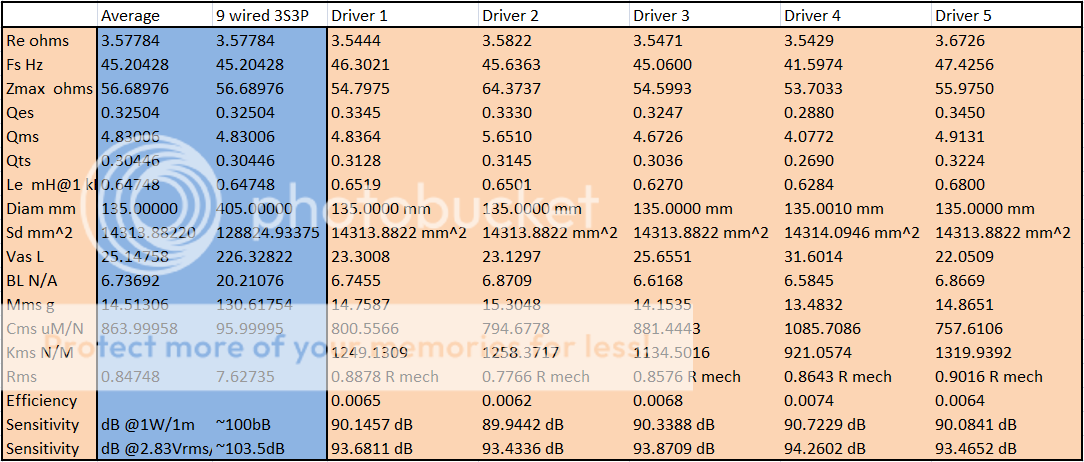
That by itself won't accurately model a line array, especially in a TL, etc, so about the best one can do in HR is to locate the line at wherever driver #5 is and hopefully the different line loading of each driver will average out 'close enough' to the one huge driver in the sim.
Anyone know if AkAbak can accurately sim this?
GM
Anyone know if AkAbak can accurately sim this?
GM
Hi Neo Dan and GM
What Hornresp does is add all the piston diameter from all the drivers into one. It will give you a green and a red circle for front and back of the same integrated piston. So I guess this works well for computational purposes but not so well for real life multi-driver situations.
I know that it can be done in AkaBak for sure. That is one evil powerful program. I know how to manipulate scripts generated through Hornresp but to go hole hog and do a multi driver model is beyond what I know currently. I have never spent the required time to really work through AkaBak. I'm getting lazy I know. But some guy named David McBean keeps making his program more powerful.
Mark
- Home
- Loudspeakers
- Subwoofers
- Hornresp