SPL/on-axis directivity
Guys, just wanted to jump in a double-check an important point here, that Lars just told me about on a thread elsewhere .
I'm designing a bass/mid Hyperbolic exponential for B&C 8PE21 , and I've got to the point of being pretty happy with it based on 'SPL' views , flat from 150 to 600 at least with low ripple .
However... I may be designing wrong, as Lars pointed out, the normal SPL graph assumes constant-directivity and this horn is probably NOT , along with Tractrix, LeCleach etc .
So, looks like I have to use the directivity>response function with a small angle ( eg. 0.5 degrees ) to evaluate my true axial response ?
If I don't address this I'm guessing I might end up with a rising on-axis response which is going to require EQ , which I'd like to avoid .
Could be this will require a re-think and possible a different pair of drivers ( lower mass-rolloff ) so I'd like to be 100% sure and if there are any other factors that come into this, please let me know .
MJ
Could you give me a hint of what to expect as a realistic on-axis response?
Hi Lars,
It is difficult to generalise - it all depends on the profile of the horn. A conical horn will tend to exhibit constant directivity characteristics whereas an exponential horn will "beam" significantly as the frequency increases. Using the Directivity > Pattern tool on different profiles at various frequencies will demonstrate this quite clearly.
Although the Hornresp directivity model is relatively sophisticated, it still only gives indicative results. Boundary Element Method (BEM) techniques really need to be used to accurately predict the directional characteristics of horn loudspeakers. Calculating the directivity of a combined response is an even more difficult task
") .
.Kind regards,
David
So, looks like I have to use the directivity>response function with a small angle ( eg. 0.5 degrees ) to evaluate my true axial response?
Hi Mark,
Just to clarify - setting the Directivity off-axis angle to zero degrees will give the axial pressure response. It is not necessary to use a small non-zero angle.
The 0 degrees off-axis directivity response is not the same as the default constant directivity response.
Kind regards,
David
Last edited:
How do I simulate a TH using two drivers in parallel with HornResp?
Hi,
I would like to simulate a Tapped Horn using two drivers mounted in parallel (see schematic below). However, I am a bit uncertain about how to do it. I have two questions:
1. Do I just insert the T/S-parameters for ONE driver, and then afterward press Tools => Driver Arrangements => 1 in series; 2 in parallel? Will that do the trick, or do I have to change some of the T/S-parameters in order to simulate two driver too?
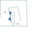
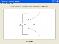
2. I want to mount the drivers as in the schematic below. What are the most correct reference points for S2 and L12 (the length of the first conical section)? Is that as indicated in the drawing, or??
Thanks a lot!
Best regards
Peter
Hi,
I would like to simulate a Tapped Horn using two drivers mounted in parallel (see schematic below). However, I am a bit uncertain about how to do it. I have two questions:
1. Do I just insert the T/S-parameters for ONE driver, and then afterward press Tools => Driver Arrangements => 1 in series; 2 in parallel? Will that do the trick, or do I have to change some of the T/S-parameters in order to simulate two driver too?
2. I want to mount the drivers as in the schematic below. What are the most correct reference points for S2 and L12 (the length of the first conical section)? Is that as indicated in the drawing, or??
Thanks a lot!
Best regards
Peter
Attachments
Hoping to find some resemblance with the combined sims
Good luck Lars
.Kind regards,
David
Hi Peter,
Yes - either the Thiele-Small or electro-mechanical parameters, whichever are known.
Note that it is not necessary to select Tools > Driver Arrangement. Simply double-click on the disabled TH text box in Edit mode to activate the tool.
Most correct as indicated in the drawing.
Hornresp simply assumes a single "composite driver" at the S2 point. Looking at the schematic diagram you will see that in this case the composite driver (two parallel drivers) has twice the area of a single driver.
It may be possible to build a more accurate model in AkAbak showing the two drivers as physically separated - not sure how different the results would be though.
Kind regards,
David
Do I just insert the T/S-parameters for ONE driver, and then afterward press Tools => Driver Arrangements => 1 in series; 2 in parallel?
Yes - either the Thiele-Small or electro-mechanical parameters, whichever are known.
Note that it is not necessary to select Tools > Driver Arrangement. Simply double-click on the disabled TH text box in Edit mode to activate the tool.
I want to mount the drivers as in the schematic below. What are the most correct reference points for S2 and L12 (the length of the first conical section)? Is that as indicated in the drawing, or??
Most correct as indicated in the drawing.
Hornresp simply assumes a single "composite driver" at the S2 point. Looking at the schematic diagram you will see that in this case the composite driver (two parallel drivers) has twice the area of a single driver.
It may be possible to build a more accurate model in AkAbak showing the two drivers as physically separated - not sure how different the results would be though.
Kind regards,
David
Hi Peter,
Yes - either the Thiele-Small or electro-mechanical parameters, whichever are known.
Note that it is not necessary to select Tools > Driver Arrangement. Simply double-click on the disabled TH text box in Edit mode to activate the tool.
Most correct as indicated in the drawing.
Hornresp simply assumes a single "composite driver" at the S2 point. Looking at the schematic diagram you will see that in this case the composite driver (two parallel drivers) has twice the area of a single driver.
It may be possible to build a more accurate model in AkAbak showing the two drivers as physically separated - not sure how different the results would be though.
Kind regards,
David
Hi David,
Thanks a lot for a guick reply!
One more question (please!):
Given your reply, I am still a bit uncertain whether the SD I type in HornResp should be for ONE or TWO drivers?
Does HornResp "know", that when I type in SD for ONE driver, and then subsequently state, that the simulation os for 2 drivers in parallel, then HornResp will "double" the SD in its simulation?
I'm sorry - I just want to get it right, before cutting anything!
Thanks a lot again!
PS: I do not want to fiddle around with AKABAK - I am very pleased with Horn Resp!
Best regards
Peter
Given your reply, I am still a bit uncertain whether the SD I type in HornResp should be for ONE or TWO drivers? Does HornResp "know", that when I type in SD for ONE driver, and then subsequently state, that the simulation is for 2 drivers in parallel, then HornResp will "double" the SD in its simulation?
Hi Peter,
Sorry to confuse you
. The Sd value you enter should be for one driver only. Hornresp automatically adjusts the value of Sd internally as necessary, when multiple drivers are specified. You can check the compression ratio to confirm this. For two drivers the tapped horn Sd / S2 value will be twice the single driver value. The size of the diaphragm shown on the schematic diagram will also change to indicate that two drivers are in use, as mentioned in my previous post.Kind regards,
David
Hi Peter,
Sorry to confuse you
Kind regards,
David
Hi David,
Thank you so much! You have been most helpful!
Best regards
Peter
Thank you so much! You have been most helpful!
You're welcome Peter
.Kind regards,
David
Directivity
Thanks for the reply earlier David.
From what you said, I understand that a listener sat in front of the ( exponential/hyperbolic) horn is going to be more interested in the axial pressure response for 0 degrees , not the default SPL graph which is a total power response ?
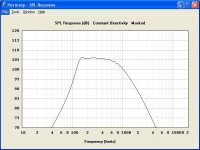
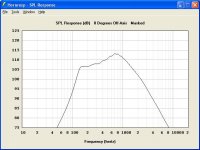
I attach two graphs , to illustrate the difference. It would seem that the design performance at present is the 'bad' one with about 7dB rise from 150 to 700Hz ? (!)
Thanks ...
MJ
Anybody want a pair of nearly-new B&C 8PE21's ?
Thanks for the reply earlier David.
From what you said, I understand that a listener sat in front of the ( exponential/hyperbolic) horn is going to be more interested in the axial pressure response for 0 degrees , not the default SPL graph which is a total power response ?
I attach two graphs , to illustrate the difference. It would seem that the design performance at present is the 'bad' one with about 7dB rise from 150 to 700Hz ? (!)
Thanks ...
MJ
Anybody want a pair of nearly-new B&C 8PE21's ?
Attachments
Hi Mark,
Correct.
The difference you are seeing is typical for a hyperbolic-exponential horn.
Don't be too hasty....
Remember that Hornresp models the driver diaphragm as a rigid plane circular piston. The actual diaphragm will behave somewhat differently to this at higher frequencies.
Also, if a phasing plug is not included in the horn design then you may find that the high frequency sound output is attenuated, thus offsetting the directivity gain to some extent.
Kind regards,
David
From what you said, I understand that a listener sat in front of the (exponential/hyperbolic) horn is going to be more interested in the axial pressure response for 0 degrees, not the default SPL graph which is a total power response?
Correct.
I attach two graphs, to illustrate the difference. It would seem that the design performance at present is the 'bad' one with about 7dB rise from 150 to 700Hz?
The difference you are seeing is typical for a hyperbolic-exponential horn.
Anybody want a pair of nearly-new B&C 8PE21's ?
Don't be too hasty...
.Remember that Hornresp models the driver diaphragm as a rigid plane circular piston. The actual diaphragm will behave somewhat differently to this at higher frequencies.
Also, if a phasing plug is not included in the horn design then you may find that the high frequency sound output is attenuated, thus offsetting the directivity gain to some extent.
Kind regards,
David
Last edited:
Thanks
Thanks David for the extra advice.
I've decided to refine the design suitable for 2 or 3 possible drivers , then trial build one horn, run with the 8PE21 , measure, then if necessary buy the most suitable pair later, maybe 8PS21 or 8NDL51 . I need to evaluate the rectangular-build horn anyway .
Mark
Hello David,
I am not sure if I have understood the instructions for combined/rear path length.
Check the attachement and tell me how the rear path length should be when moving the vent to the same plane as the horn mouth. Zero or -60cm?
I am not sure if I have understood the instructions for combined/rear path length.
Check the attachement and tell me how the rear path length should be when moving the vent to the same plane as the horn mouth. Zero or -60cm?
Attachments
Last edited:
Hi All, I have two dumb questions.
1. When I model a horn and give the mouth dimentions and get the results I am looking for, does it matter if the horn is square, rectangle, round as long as it is the right size?
2. When I model a horn and get SPL responce graph, how do I interpret what is going to happen at higher freqs than what the graph shows as the high end roll-off? Assuming my driver goes higher than the highend roll-off shown in the graph.
Hi All, I have two dumb questions.
1. When I model a horn and give the mouth dimentions and get the results I am looking for, does it matter if the horn is square, rectangle, round as long as it is the right size?
2. When I model a horn and get SPL responce graph, how do I interpret what is going to happen at higher freqs than what the graph shows as the high end roll-off? Assuming my driver goes higher than the highend roll-off shown in the graph.
1. Square will be close to round of the same area, but rectangular will not be so close, and further off as frequency increases.
2. There are too many variables in cone breakup, suspension oddities, narrowing beamwidth etc. to assume anything above the high end roll-off.
If you are afraid to waste some wood, a scissors, cardboard and some duct tape will give you a very good idea of what your horn design will sound like, long as you don't turn it up too loud.
One can often find a kitchen pot that will work for a compression chamber too, but the cook may not approve it's use, and duct tape residue can be tough to remove..
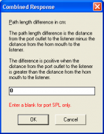
I am not sure if I have understood the instructions for combined/rear path length. Check the attachment and tell me how the rear path length should be when moving the vent to the same plane as the horn mouth. Zero or -60cm?
Hi Lars,
In Hornresp, for the example you have given, the path length difference is defined as the distance from the port outlet to the listener minus the distance from the horn mouth to the listener.
1. If the acoustic path length from the port outlet to the listener is the same as the acoustic path length from the horn mouth to the listener, then the path length difference will be zero cm.
2. If the acoustic path length from the port outlet to the listener is 10 cm greater than the acoustic path length from the horn mouth to the listener, then the path length difference will be 10 cm.
3. If the acoustic path length from the port outlet to the listener is 10 cm less than the acoustic path length from the horn mouth to the listener, then the path length difference will be -10 cm.
Note that the path length difference relates to acoustic path lengths external to the speaker system, not to acoustic path lengths internal to the speaker system.
The attachment below refers.
EDIT - I just realised that you might still be confused after reading my explanation above
. The direct answer to your question is zero cm for the example you have given. The fact that the horn mouth and port outlet are not aligned in the same plane in the schematic diagram does not matter - it all depends on how the system is actually physically configured in practice, in relation to the listener.Kind regards,
David
Attachments
Last edited:
- Home
- Loudspeakers
- Subwoofers
- Hornresp