How about a sixth order vented system, an active boost, very rapid cutoff, much less over-excursion of the cone!That is basically the same thing as a LT filter, just the name (and parameters) are different.
I personally don't think it's very useful to compensate a ported design for the reasons mentioned.
But technically it's an option, can be done and might be useful in some cases.
Stacking a bunch of param EQ can also give the same or a very similar result as a LT btw.
For those who don't have the LT option in their DSP settings.

I have already made the first series 6th order pic, but after a lot of modelling, I came to the conclusion that the second design is much better for me.
So I just need to open it up and change it.
But this is a 45kg subwoofer on 8kW and the baffle in the middle is 5,6cm thick, so I wouldn't want to cut it open any more than I have to, because it is structurally important and it would be hard to cut.
So it basically becomes an 8th order box if I don't cut it down any, but I couldn't find an 8th order model in Hornresp that matches this type.
Basically a double chamber reflex with a common front chamber for the second port and driver.
Can anyone recommend a way to model this second enclosure even remotely closer than the series 6th model?
Can anyone recommend a way to model this second enclosure even remotely closer than the series 6th model?
It cannot be done in Hornresp. You would need to use AkAbak.
Hornresp Update 5540-240412
Hi Everyone,
CHANGE
A Linkwitz Transform equalisation correction can now be applied to a closed-box enclosure loudspeaker system by double-clicking on the High Pass filter option in the Filter Wizard parametric equaliser filter band 1.
The Linkwitz Transform correction enables the response of a closed-box loudspeaker to be extended to a specified lower frequency fp.
The Linkwitz Transform gain should not exceed 12 dB and the k parameter value should be greater than zero.
Linkwitz Transform input parameters:
fo = Natural fc (system fundamental resonant frequency)
Qo = Natural Qtc (system total quality factor Q)
fp = Target fc
Qp = Target Qtc
fo and Qo values are calculated automatically.
fp and Qp values are specified by the user.
BUG FIX
The problem of not being able to create new data files as reported in Post #14,547 has now been fixed. My thanks to enyerson for making me aware of the issue.
Kind regards,
David
Attachments
Can anyone recommend a way to model this second enclosure even remotely closer than the series 6th model?
Maybe the Hornresp Paraflex Model Type 1 or type 2 can be used to give you an approximation.
Thank you very much for implementing it and thank you for developing this great programA Linkwitz Transform equalisation correction can now be applied to a closed-box enclosure loudspeaker system by double-clicking on the High Pass filter option in the Filter Wizard parametric equaliser filter band 1.
Hi David, would you mind explaining your reasons for this please?The Linkwitz Transform gain should not exceed 12 dB
I've recently build a closed box subwoofer with HR and used the Peq function to great effect to extend is useful low end.
Thanks for such a great tool.
Hi David, would you mind explaining your reasons for this please?
Hi Mazza,
The recommended maximum gain was set at 12 dB simply to keep input power and diaphragm displacement to reasonable levels at low frequencies.
Another update is required to address a few things that were missed in the initial Linkwitz Transform implementation and after thinking about it some more as a result of your post, the 12 dB reference will be removed from the Help File as part of that update. It will be left to the user to decide what is an appropriate practical gain for a given design.
Kind regards,
David
@David McBean
Practically I usually don't even recommend going over 6dB.
6dB of boost mean double the voltage of the signal. 10^6/20 = 2
So it's quite easy to clip either the amplifier, preamp or DAC with this.
Even the headroom of the DSP needs to be watched, but often this quite a bit higher.
Practically I usually don't even recommend going over 6dB.
6dB of boost mean double the voltage of the signal. 10^6/20 = 2
So it's quite easy to clip either the amplifier, preamp or DAC with this.
Even the headroom of the DSP needs to be watched, but often this quite a bit higher.
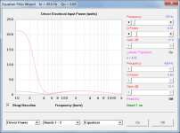
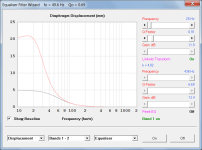
The recommended maximum gain was set at 12 dB simply to keep input power and diaphragm displacement to reasonable levels at low frequencies.
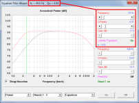
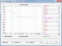
To illustrate the effect, the attachments below show input power and diaphragm displacement with and without a Linkwitz Transform applied. The same closed box example as before is used, with Eg set to 8.94 volts (10 watts into 8 ohms).
Red trace - Linkwitz Transform On
Grey trace - Linkwitz Transform Off
Practically I usually don't even recommend going over 6dB.
Another good reason not to prescribe an arbitrary 12 dB limit...
Attachments
I usually also always add at least a 1st order high pass filter or otherwise very low freq param EQ attenuator when a LT EQ is being used.
Otherwise you run the risk of sending your beloved driver to the trash bin in an instance.
All that being said, the graph you're showing doesn't take the non-linear Cms(x) into consideration.
So in practice it's not nearly as bad.
Otherwise you run the risk of sending your beloved driver to the trash bin in an instance.
All that being said, the graph you're showing doesn't take the non-linear Cms(x) into consideration.
So in practice it's not nearly as bad.
Even if you do have the ability to model it, it is only as useful as a indication anyway. There are variances in all the soft parts of loudspeakers. The better parts vendors keep strict quality control. But rarely are spiders and surrounds given the proper attention that they deserve.I usually also always add at least a 1st order high pass filter or otherwise very low freq param EQ attenuator when a LT EQ is being used.
Otherwise you run the risk of sending your beloved driver to the trash bin in an instance.
All that being said, the graph you're showing doesn't take the non-linear Cms(x) into consideration.
So in practice it's not nearly as bad.
Secondarily there should be viable QC in the factory that produces your drivers, or again, you get whatever they send to you from the unqualified parts vendors.
Long and short. Modeling such effects is next to impossible with any level of accuracy that brings you useful information.
Some simple standard deviation on Klippel LSI results on a bunch of samples.Long and short. Modeling such effects is next to impossible with any level of accuracy that brings you useful information.
They have been doing similar things for the last 50 years (at least) on electronics components.
I agree!They have been doing similar things for the last 50 years (at least) on electronics components.
I even work with a build house that does this with every part of the driver. But that is an exceptional rarity.
Finding a machine that will rapidly test the CMS of a damper or spider was the begining of doing it consistently.
Hornresp Update 5540-240416
Hi Everyone,
CHANGE 1
The reference to a 12 dB limit on the gain of a Linkwitz Transform filter has been removed from the Help File, and the Filter Wizard LT Gain slider value no longer changes to bold red font when greater than 12 dB. Post #14,568 refers.
CHANGE 2
The Linkwitz Transform fo and Qo values are now only shown in the Filter Wizard caption when the following conditions apply:
Bands 1 - 2 input option selected.
Band 1 Linkwitz Transform option selected.
Band 1 switched on.
BUG FIX 1
Previously when a closed box system that had a Linkwitz Transform filter specified was changed to some other non-sealed design, the existing LT filter could still be applied to the new design. This incorrect operation is no longer possible.
BUG FIX 2
Previously if equaliser band 1 had a Linkwitz Transform filter specified and it was switched off and the filter wizard then closed, the band 1 filter would be automatically switched back on when the wizard was reopened. This has now been fixed so that band 1 remains switched off.
BUG FIX 3
Previously if a Linkwitz Transform filter was used when producing main chart results, and the filter was then switched off, the red "Equaliser Filter" note would still be displayed at the lower left of the main chart. This has now been fixed so that the note is no longer displayed.
Kind regards,
David
- Home
- Loudspeakers
- Subwoofers
- Hornresp