Maybe the default loading for Hornresp should be switched to 2.0*Pi for new sims? This should make the predicted results be more closely aligned to what other box modeling programs predict and should minimize the occurrence of this type of simple error.
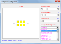
It is interesting that corner loading (Ang = 0.5 * Pi) is assumed and that the driver and transmission line outputs are co-located (Path = 0.00 cm). A smaller a system with a wider response could perhaps have been produced using the Transmission Line Loudspeaker Design Wizard optimisation tool (Tools > Design Wizard > Transmission Line).
Corner loading I figure is how many walls the speaker is interacting with (going off the picture differences in the video) after that I am sorry I have no idea what you just said.
What does Nd actually denote? The text at the bottom of the screen says "Nd Single driver" so I took that to mean one driver in the box, as in a single driver, but then he changed it to OD (which is still only one driver but offset from the end, so I kind of get that it might be called OD or Nd OD). Have I understood that right?
But is that realistic? It might make it more like other software, but isn't the point of the exercise to make it reflect what the speaker is going to do in the average room? How close to a wall do you need to be before it counts?Maybe the default loading for Hornresp should be switched to 2.0*Pi for new sims? This should make the predicted results be more closely aligned to what other box modeling programs predict and should minimize the occurrence of this type of simple error.
It's very realistic when no 2 rooms are alike. Outside ground plane measurements are the only way you can tell if you built what you modeled.
Look at Bose. They built dedicated rooms for their HTS' which prevented you from comparing their speakers to other speakers in the exact same environment.
Look at Bose. They built dedicated rooms for their HTS' which prevented you from comparing their speakers to other speakers in the exact same environment.
Last edited:
Maybe the default loading for Hornresp should be switched to 2.0*Pi for new sims?
You make a good point but I would rather not change the default record now because of its historical significance. Hornresp was written originally for the sole purpose of analysing the performance of a Klipschorn, the definitive corner-loaded horn loudspeaker.
The Hornresp default record is in effect an example of a Klipschorn-type design
") .
.The person who made the video was certainly aware that it was possible to specify a different Ang value, but he seemed to think that it only changed the absolute level and so left it at the default of 0.5 * Pi. He did not appear to appreciate that the response at bass frequencies could also be affected specifically, depending upon the value chosen.
Corner loading I figure is how many walls the speaker is interacting with
Correct.
after that I am sorry I have no idea what you just said.
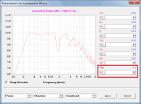
The transmission line loudspeaker is analysed as a system having two point source acoustic outputs. The first output is from the front radiating side of the driver and the second output is from the opening at the end of the transmission line. When combining the two outputs to calculate the overall power response, the result will be more accurate if the distance separating the two point source outputs is taken into account. This is done using the Path length parameter.
In the case of the system shown in the video, the separation distance is acoustically quite small at bass frequencies so leaving the value at zero doesn't make much of a difference to the results, but it is still good practice to specify the Path length anyway.
The Transmission Line Loudspeaker Design Wizard tool is a relatively recent addition to Hornresp. It uses methods developed by Martin King and Brian Steele to assist in the production of TL designs optimised in terms of size and performance.
What does Nd actually denote?
Originally Hornresp could only simulate standard front-loaded and back-loaded horn loudspeakers, and the Nd label at that time stood for "number of drivers". When other configurations such as OD were added, Nd came to mean "normal driver".
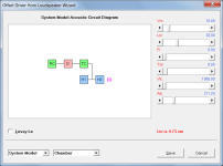
The number of drivers in the system being simulated are shown in the driver configuration box alongside the label. For example, OD = 2P 3S means that the loudspeaker has a total of six offset drivers made up of two groups connected electrically in parallel, with each group containing three drivers connected in series, as shown in the attachments.
Attachments
just double click one of the segment surfaces (e.g. S2, S1 cannot be split up). this turns the "S" red and splits them up into "S2" and "S2S", for example.How do you separate segments
The guy in the video admitted he was very confused by the software, and I assume that is why he set a value of 0 for those six boxes at the very bottom. Like him I have no clue what any of them mean or do, so letting us know it is Ok to set them to zero is one small step forward from what I know to do with them. If one of those the Path Length parameter?if the distance separating the two point source outputs is taken into account. This is done using the Path length parameter.
In the case of the system shown in the video, the separation distance is acoustically quite small at bass frequencies so leaving the value at zero doesn't make much of a difference to the results, but it is still good practice to specify the Path length anyway.
By path length are you talking about the total length of the path, or as the crow flies between the driver and the port? I could see how that might be factored into the overall SPL.
Or, use 0.01 as the segment length.Sorry to ask, but it's a long thread to read through.
How do you separate segments to make sudden area changes in one spot?
Like this:
View attachment 1279886
In the example below, there is no Segment 3 in the Schematic Diagram window.
Last edited:
Corner loading I figure is how many walls the speaker is interacting with
Further to my earlier one-word "Correct" response...
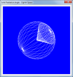
As far as Hornresp is concerned, corner loading means that the loudspeaker is radiating into eighth space, or a solid angle of 0.5 * Pi steradians.
https://en.wikipedia.org/wiki/Solid_angle
Attachments
How do you separate segments to make sudden area changes in one spot?
See highlighted section in attached Help File extract.
Attachments
Like him I have no clue what any of them mean or do
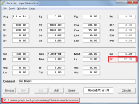
The six boxes at the bottom of the Input Parameters window contain chamber parameter values. Moving the mouse pointer over any of the boxes displays an explanatory note in the status bar panel at the bottom of the window.
Vrc specifies the rear chamber volume in litres.
Lrc specifies the rear chamber length in centimetres.
Fr specifies the airflow resistivity of any acoustical material lining the rear chamber in mks rayls/m.
Tal specifies the thickness of the acoustical lining material in centimetres.
Vtc specifies the volume of the throat chamber in cubic centimetres.
Atc specifies the cross-sectional area of the throat chamber in square centimetres (when used, Atc is often set equal to Sd).
The above are general parameters, and can be used in a number of different loudspeaker systems.
In the case of an offset driver transmission line design, a rear chamber is not required, which is why Vrc, Lrc, Fr and Tal are set to zero. The design in the video makes no allowance for a throat chamber which is why Vtc and Atc are also set to zero.
Attachment 1 shows the OD transmission line System Model with rear and throat chambers included. RC shows the position of the rear chamber in relation to driver D and TC shows the position of the throat chamber.
If one of those the Path Length parameter?
The Path length parameter is separate from the above-mentioned chamber parameters, as shown in Attachment 2.
By path length are you talking about the total length of the path, or as the crow flies between the driver and the port?
The Path length is the distance the crow would fly. It is as if the enclosure itself does not exist, and the two acoustic sources (driver and port) are simply suspended in space separated by the Path length distance. The distance is measured from the centre of source 1 to the centre of source 2.
Attachments
Last edited:
A lot of math there, but I kind of understand it to mean that it depends upon what is blocked from the point of the observer. As per their moon / sun example.Further to my earlier one-word "Correct" response...
As far as Hornresp is concerned, corner loading means that the loudspeaker is radiating into eighth space, or a solid angle of 0.5 * Pi steradians.
https://en.wikipedia.org/wiki/Solid_angle
So I am guessing then a chamber only becomes a chamber when it is physically isolated from the other parts of the cabinet.In the case of an offset driver transmission line design, a rear chamber is not required, which is why Vrc, Lrc, Fr and Tal are set to zero. The design in the video makes no allowance for a throat chamber which is why Vtc and Atc are also set to zero.
@ David
Has anyone asked if an expanded Db scaling is possible? Sometimes I am trying to tickle a few db between designs and it can be rather difficult to show people that there is actually a difference between the two. The project is for pro-sound and 2 db is not a small gain in the real world. But it looks so tiny on the graphs!
Has anyone asked if an expanded Db scaling is possible? Sometimes I am trying to tickle a few db between designs and it can be rather difficult to show people that there is actually a difference between the two. The project is for pro-sound and 2 db is not a small gain in the real world. But it looks so tiny on the graphs!
Well, consider me schooled. But I would still wish for 1 dog bone resolution. I guess that this is a unique application situation. Midrange efficiency on a very high efficiency pro-sound driver. My design software is good, but it is always better to check with something else that is tried, tested and true. Like Hornresp!Double click on the graphs to show every 3 dB's. That's my next step after clicking on Calculate.
A lot of math there
The only two formulas of interest to Hornresp are:
A = 4 * pi * r ^ 2
Where:
A = surface area of sphere
r = radius of sphere
And:
Ang = A1 / (r ^ 2)
Where:
Ang = solid angle of spherical sector
A1 = curved surface area of spherical sector (on surface of sphere)
r = radius of sphere
If a loudspeaker is radiating from a corner into eighth space then the loudspeaker will "see" only one-eighth of the surface area of a sphere centred on the corner apex.
This means that:
A1 = A / 8
And:
Ang = (A / 8 ) / (r ^ 2)
Ang = ((4 * pi * r ^ 2) / 8 ) / (r ^ 2)
Ang = 0.5 * Pi
I kind of understand it to mean that it depends upon what is blocked from the point of the observer. As per their moon / sun example.
If by observer you mean the loudspeaker and not the listener, then yes, you understand correctly.
- Home
- Loudspeakers
- Subwoofers
- Hornresp