BR:
Vb=15*Vas(Qts^2.87)
Fb=0.42*Fs(Qts^-0.9)
Port calculation was already discussed somewhere above, but for the record, here a simple( and probably not reliable) formula:
Choose R, e.g. R=3 In
Lv=(1.463*(10^7)*(R)^2/(Fb^2)(Vb))-(1.463)*R
Sealed enclosure:
X=(0.70/Qts)^2-1
Vb=Vas/X
Unfortunately the above equations are not robust enough for inclusion in Hornresp. Depending on the values chosen for driver fs, Vas and Qts, it is quite easy to obtain sub-optimal outcomes. Does anyone know of alternative closed box and bass reflex formulas that do indeed produce optimum values for Vb in litres, and Lv in cm?
when I save the file it defaults back to '7'.
Your post prompted me to have another look at the issue. By multi-tasking an existing field in the data record hopefully it should be possible to permanently save the QL setting value without the need for an extra field. If all goes according to plan the enhancement will be included in the next update. Thanks for raising the matter!
Unfortunately the above equations are not robust enough for inclusion in Hornresp. Depending on the values chosen for driver fs, Vas and Qts, it is quite easy to obtain sub-optimal outcomes. Does anyone know of alternative closed box and bass reflex formulas that do indeed produce optimum values for Vb in litres, and Lv in cm?
These are the ones that I used to use.
Vb=(20*Qts^3.3)*Vas
Fb=((Vas/Vb)^0.31)*Fs
They assume Ql=7
It's basically a curve-fit for a maximally-flat alignment with the smallest enclosure and lowest F3, using the data given in the tables in the LDC, if I remember correctly.
These are the ones that I used to use.
Thanks Brian.
Q1 - Do your Vb and Fb formulas apply to a closed-box system, to a bass-reflex system, or to both?
Q2 - If they are the formulas that you used to use, what do you use now to design a closed-box or bass-reflex system?
Q3 - What formula should be used to calculate port tube length Lv for a bass-reflex system?
The formula I provides applies only to vented alignments.
I don't use them any more because a "maximally-flat" alignment might not be the best option for a given driver, and in any case the formula does not take the driver's inductance (or semi-inductance) into account.
I don't use a formula to derive Lv from Fb and Fb and Dv. I use Hornresp and manually adjust Lv until I get the Fb I'm looking for")
I don't use them any more because a "maximally-flat" alignment might not be the best option for a given driver, and in any case the formula does not take the driver's inductance (or semi-inductance) into account.
I don't use a formula to derive Lv from Fb and Fb and Dv. I use Hornresp and manually adjust Lv until I get the Fb I'm looking for
How do I simulate a dual opposing sub drivers vented enclosure in HornResp?
You can take some information in the website below. Check the models with the DUAL word in the name, like the Manifold-1-Dual, you can check the model and also download the files to check from where the information come from inside the datasheet. There are tutorial videos available in case you need.
https://freeloudspeakerplan.rf.gd
Thank you Lord!
There isn't a model that is like I'm looking for in there.
It's a bit like the VBSLOT1-a, but I want the drivers to shoot in push-push configuration (parallel wiring, so vibrations cancel each other), with the port facing the listener, like the picture below.

There isn't a model that is like I'm looking for in there.
It's a bit like the VBSLOT1-a, but I want the drivers to shoot in push-push configuration (parallel wiring, so vibrations cancel each other), with the port facing the listener, like the picture below.
Hi Perceval!
That's still just two parallel drivers in an enclosure. The mechanical vibrations are not accounted for in Hornresp, so force cancellation is not visible there. Hornresp will assume same distance from the two driver to microphone/ear. Push-push into a slot introduces additional load on the cone, but push-push into the open is acoustically identical to having the drivers on the same baffle. Not saying that it isn't a good idea to do this
/onni
There isn't a model that is like I'm looking for in there.
The page can inspire you and help you to understand how to model a box and then with knowledge you can adjust the model to better cover your case.
From may point of view that model is exactly the model needed for your case but you also need to change the combined output and change distance between sources (Vent and Driver) once they are not aligned as in the model or depending from the frequency you can consider they are aligned, it depends from the size of the wave of the frequency you want to reproduce trough the vent.
Hornresp Update 5510-231013
Hi Everyone,
CHANGE 1
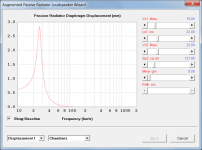
An augmented passive radiator displacement chart option has now been added to the Loudspeaker Wizard. Attachment 1 and Post #13,963 refer.
As expected, the APR displacement tends towards zero as the value of Sp2 approaches that of Sp1. Also as expected, if Sp2 is set to zero then the APR displacement will be identical to that of a conventional passive radiator having the same Sp1, Cmp, Mmp and Rmp values.
CHANGE 2
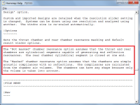
Additional information relating to the 'Masked' and 'Not masked' chamber resonance options has been included in the Help file. Attachment 2 and Post #13,961 refer.
CHANGE 3
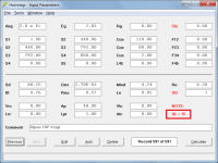
QL values can now be permanently saved to the Hornresp.dat data file rather than being reset back to the default of 7 when a new record is added or a different existing record is selected. Attachment 3 and Post #13,969 refer.
CHANGE 4
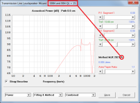
Alignment information is now displayed on the Transmission Line Loudspeaker Wizard caption line when the Method MJK 2021 A, B or C option is selected. Attachment 4 refers.
CHANGE 5
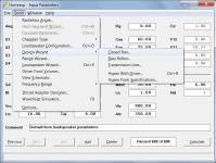
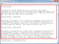
5.1 The old Tools menu System Design command has been renamed Design Wizard.
5.2 Closed Box is a new sub-menu command under Design Wizard.
5.3 Base Reflex is a new sub-menu command under Design Wizard.
5.4 The old TL Design menu is now a sub-menu command named Transmission Line under Design Wizard.
5.5 The old With Driver sub-menu command, now under Design Wizard, has been renamed Hypex With Driver.
5.6 The old From Specifications sub-menu command, now under Design Wizard, has been renamed Hypex From Specifications.
Attachments 5 and 6 refer.
The newly-added Closed Box and Bass Reflex design tools use the 'with driver' procedures documented in the Marshall Leach book: "Introduction to Electroacoustics and Audio Amplifier Design". Post #13,965 refers. The usefulness of the calculated results appears to depend significantly upon the suitability of the specified driver.
BUG FIX
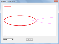
A bug in the Visual Basic compiler itself rather than in the Hornresp source code meant that when previewing a rectangular cross-section horn prior to exporting the data, under certain conditions the profile diagram could be displayed incorrectly, as shown in the Attachment 7 example. A workaround has now been put in place to overcome the problem.
Kind regards,
David
Hi Everyone,
CHANGE 1
An augmented passive radiator displacement chart option has now been added to the Loudspeaker Wizard. Attachment 1 and Post #13,963 refer.
As expected, the APR displacement tends towards zero as the value of Sp2 approaches that of Sp1. Also as expected, if Sp2 is set to zero then the APR displacement will be identical to that of a conventional passive radiator having the same Sp1, Cmp, Mmp and Rmp values.
CHANGE 2
Additional information relating to the 'Masked' and 'Not masked' chamber resonance options has been included in the Help file. Attachment 2 and Post #13,961 refer.
CHANGE 3
QL values can now be permanently saved to the Hornresp.dat data file rather than being reset back to the default of 7 when a new record is added or a different existing record is selected. Attachment 3 and Post #13,969 refer.
CHANGE 4
Alignment information is now displayed on the Transmission Line Loudspeaker Wizard caption line when the Method MJK 2021 A, B or C option is selected. Attachment 4 refers.
CHANGE 5
5.1 The old Tools menu System Design command has been renamed Design Wizard.
5.2 Closed Box is a new sub-menu command under Design Wizard.
5.3 Base Reflex is a new sub-menu command under Design Wizard.
5.4 The old TL Design menu is now a sub-menu command named Transmission Line under Design Wizard.
5.5 The old With Driver sub-menu command, now under Design Wizard, has been renamed Hypex With Driver.
5.6 The old From Specifications sub-menu command, now under Design Wizard, has been renamed Hypex From Specifications.
Attachments 5 and 6 refer.
The newly-added Closed Box and Bass Reflex design tools use the 'with driver' procedures documented in the Marshall Leach book: "Introduction to Electroacoustics and Audio Amplifier Design". Post #13,965 refers. The usefulness of the calculated results appears to depend significantly upon the suitability of the specified driver.
BUG FIX
A bug in the Visual Basic compiler itself rather than in the Hornresp source code meant that when previewing a rectangular cross-section horn prior to exporting the data, under certain conditions the profile diagram could be displayed incorrectly, as shown in the Attachment 7 example. A workaround has now been put in place to overcome the problem.
Kind regards,
David
Attachments
in the TL design MJK 2021 options, are the volumes still based on the LDC tables?The newly-added Closed Box and Bass Reflex design tools use the 'with driver' procedures documented in the Marshall Leach book:
The three MJK 2021 options still use the following Vance Dickason 'Loudspeaker Design Cookbook' tables:
Option A - Table 2.3 - Alignment SBB4 and BB4 QL = 15
Option B - Table 2.6 - Alignment QB3 and SQB3 QL = 15
Option C - Table 2.9 - Alignment SC4 and C4 QL = 15
Option A - Table 2.3 - Alignment SBB4 and BB4 QL = 15
Option B - Table 2.6 - Alignment QB3 and SQB3 QL = 15
Option C - Table 2.9 - Alignment SC4 and C4 QL = 15
The newly-added Closed Box and Bass Reflex design tools use the 'with driver' procedures documented in the Marshall Leach book: "Introduction to Electroacoustics and Audio Amplifier Design".
Wasn't aware of it, but at $240 can't justify it for myself, though from the Index sure looks like a 'must have' for someone wanting it all in one place to learn and/or refresh one's memory..........

The newly-added Closed Box and Bass Reflex design tools use the 'with driver' procedures documented in the Marshall Leach book: "Introduction to Electroacoustics and Audio Amplifier Design".
The Marshall Leach 'with driver' procedures used in Hornresp can be downloaded by clicking on the 'Closed-Box Loudspeaker Design' and 'Vented-Box Loudspeaker Design' links at the following site: https://leachlegacy.ece.gatech.edu/audiothings.html
Yeah, being local with some Ga. Tech grad buddies I imagine I can get one from its library.There may be a copy in one of the public libraries to borrow.
- Home
- Loudspeakers
- Subwoofers
- Hornresp