https://www.parts-express.com/pedocs/specs/294-6058--bc-15ds115-4-spec-sheet.pdfI'm not entirely sure how to view the schematics.
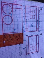
In that most basic drawing with pencil and pink marker, I do not see any opening. I would think that there should be some aperture at the end of those slowly expanding horn segments. But if those pink round marks are some sort of port that means that you either intend to have three ports up to a different volume or just ending on one side of the enclosure.
"Perfect alignment"... Sounds like marketing to me. Or are you talking about symmetry?
At any rate, you say that the schematics are open to interpretation, do you have any specific driver in mind?
Edit:
The more I look at those drawings, the more I think bandpass. I doubt the expanding segments would make much of a difference in a bandpass enclosure, seeing as there seems to be a 200cm2(?) port about 120-140cm long at the end of it.
Thanks Kaffi,
I like these thetre fun!?
I don’t know if putting a drawing up would help or hinder. it’s kind of confusing as a three dimensional layout.
0-90 cm (three times on the front output) and only once (90)on the rear. Drivers centered on 30 cm from the start on both sides .
technically four doesn’t fit , Drawing originally for another driver.. (2 instead)
Attachments
Last edited:
Thanks a lot for the help offered.Once you finalize on a design I can help you figure out the layout part. So can quite a few other gentlemen. As for tapered line you are dictating the surface area of the beginning and ending of each section. So if you want to tapper the line you reduce the cross sectional area as you proceed down the length of the line.
The way to envision what you are doing in Hornresp is a series of boxes that you have in the S1-S2, S2-S3, S3-S4 and S4-S5. These are each a section of a tube that you are dictating the surface area and length of the beginning and end of each section. The loudspeaker is installed on the side of the beginning as an offset driver OD horn. When you are interested in generating information for the output you go to the schematic page and use the File button. Export horn data. Rectangular horn. Width flare can be Uni And you adjust the width to the desired internal width of your planned enclosure. Increment is how many times you wish Hornresp to generate the area calculation over the length of the section. I usually set this to 10 for a simple horn. It limits the amount of data generated.
https://www.diyaudio.com/community/threads/help-how-to-proper-fold-a-horn.298766/post-4875332
I’ll play with the design and will get back to you. Much appreciated
It seems like nobody has heard from David in months now... Is he OK? I hope he is well!Hi all,
I received a note from David that he will not be able to post to this thread or answer e-mails until further notice, and he asked me to let you know.
I've been corresponding with him on and off, and he is well, no need to worry. He hopes to be back online in the not too distant future.It seems like nobody has heard from David in months now... Is he OK? I hope he is well!
Hornresp Update 220415
Hi Everyone,
CHANGE
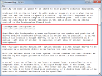
Help File loudspeaker models…
Direct Radiator in a Closed-Box Enclosure
Direct Radiator in a Closed-Box Enclosure With Offset Driver
Direct Radiator in a Closed-Box Enclosure With Offset Driver and Stub
Direct Radiator in a Closed-Box Enclosure With Passive Radiator
Direct Radiator in a Closed-Box Enclosure With Offset Passive Radiator
Direct Radiator in a Vented-Box Enclosure
Direct Radiator in a Vented-Box Enclosure With Offset Port
Offset Driver And Offset Port System With Closed Rear Chamber
Offset Driver And Offset Passive Radiator System With Closed Rear Chamber
…have been re-named and re-ordered as follows:
Closed-Box With Inline Driver
Closed-Box With Inline Driver and Passive Radiator
Closed-Box With Offset Driver
Closed-Box With Offset Driver and Stub
Closed-Box With Offset Driver and Passive Radiator
Closed-Box With Closed Rear Chamber and Offset Driver and Passive Radiator
Vented-Box With Inline Driver and Port
Vented-Box With Offset Driver and Port
Vented-Box With Closed Rear Chamber and Offset Driver and Port
Also, the Help file descriptions of the above models have been changed to hopefully more clearly explain how to specify the loudspeaker types in Hornresp.
BUG FIXES
Several minor user interface issues have now been addressed.
Kind regards,
David
Hi Everyone,
CHANGE
Help File loudspeaker models…
Direct Radiator in a Closed-Box Enclosure
Direct Radiator in a Closed-Box Enclosure With Offset Driver
Direct Radiator in a Closed-Box Enclosure With Offset Driver and Stub
Direct Radiator in a Closed-Box Enclosure With Passive Radiator
Direct Radiator in a Closed-Box Enclosure With Offset Passive Radiator
Direct Radiator in a Vented-Box Enclosure
Direct Radiator in a Vented-Box Enclosure With Offset Port
Offset Driver And Offset Port System With Closed Rear Chamber
Offset Driver And Offset Passive Radiator System With Closed Rear Chamber
…have been re-named and re-ordered as follows:
Closed-Box With Inline Driver
Closed-Box With Inline Driver and Passive Radiator
Closed-Box With Offset Driver
Closed-Box With Offset Driver and Stub
Closed-Box With Offset Driver and Passive Radiator
Closed-Box With Closed Rear Chamber and Offset Driver and Passive Radiator
Vented-Box With Inline Driver and Port
Vented-Box With Offset Driver and Port
Vented-Box With Closed Rear Chamber and Offset Driver and Port
Also, the Help file descriptions of the above models have been changed to hopefully more clearly explain how to specify the loudspeaker types in Hornresp.
BUG FIXES
Several minor user interface issues have now been addressed.
Kind regards,
David
Hornresp
Is there a cunning way to model a Ripole / SLOB (Slot Loaded Open Baffle low frequency woofer) in Hornresp?
This open baffle uses the central slot to load the woofers. The slot faces the listener. Output from the slot is velocity loaded.
Not that I am aware of. I know that a number of people have tried to simulate a Ripole using Hornresp, but I am not sure how successful they have been.Is there a cunning way to model a Ripole / SLOB (Slot Loaded Open Baffle low frequency woofer) in Hornresp?
Hi David - if you get a free moment and have the inclination, it'd be great to hear your input on something.
I've been trying to figure-out how to least-violate modeling assumptions in closed 3- and 4- segment ODO(F)P enclosures. I exaggerated some quick examples for illustration. Basically, open ended 3- and 4-seg track together, but sometimes my closed designs get in realms where it's not so obvious how to best approximate things. Thinking that almost everything axial/longitudinal that happens at lower-frequencies violates all assumptions for 1-D no matter what, but trying to do the least damage. If you have guidance, it'd be great to hear. Thank you!
I've been trying to figure-out how to least-violate modeling assumptions in closed 3- and 4- segment ODO(F)P enclosures. I exaggerated some quick examples for illustration. Basically, open ended 3- and 4-seg track together, but sometimes my closed designs get in realms where it's not so obvious how to best approximate things. Thinking that almost everything axial/longitudinal that happens at lower-frequencies violates all assumptions for 1-D no matter what, but trying to do the least damage. If you have guidance, it'd be great to hear. Thank you!
Attachments
Hi David - if you get a free moment and have the inclination, it'd be great to hear your input on something.
Hi grindstone,
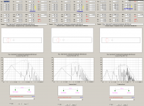
Thanks for posting the test examples. The results for all three systems should be effectively identical. It seems that there is something wrong with the 3 segment model. I need to investigate...
Kind regards,
David
It seems that there is something wrong with the 3 segment model. I need to investigate...
I found the problem, it will be fixed in the next update. It was actually the 4 segment results that were incorrect.
The results for all three examples are now identical to 4 decimal places - see attachments.
Attachments


If I'm not mistaken you keep the single driver parameters, and indicate you are using four of them. Then you increase the horn parameters.. EG cross sectional area but not length.
You can also investigate changing the radiation space instead of doing any of this. The results should be the same but I suspect these options are suited to particular situations.
Let me know if you'd like this moved to the main hornresp thread...
You can also investigate changing the radiation space instead of doing any of this. The results should be the same but I suspect these options are suited to particular situations.
Let me know if you'd like this moved to the main hornresp thread...
Hi,
Looking for a little hand holding with modelling my first isobaric subwoofer enclosure in hornresp. Any suggestions for getting started? I can get the T/S specs in well enough for reflex and sealed boxes but am new to the more advanced box simulation work.
Thanks regardless,
Looking for a little hand holding with modelling my first isobaric subwoofer enclosure in hornresp. Any suggestions for getting started? I can get the T/S specs in well enough for reflex and sealed boxes but am new to the more advanced box simulation work.
Thanks regardless,
Hi sellurstuff,Hi,
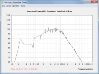
I'm working on a back loaded sub horn and wanted to simulate the response of 4 of them in a rig.
Can I just put 4 drivers in parallel in the Nd section? Or do I need to multiply the Sd by 4 as well?
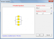
Calculate the power response for your single back loaded horn system, and then use the Multiple Speakers tool to specify 4 units in parallel.
Kind regards,
David
Attachments
Hi buildafriend,Looking for a little hand holding with modelling my first isobaric subwoofer enclosure in hornresp.
Further to GM's comments, see attachments below.
Kind regards,
David
Attachments
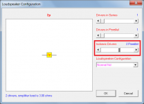
Correct. Hornresp will do the math for you if you use the multiple speakers tool. Be sure to watch your impedance and adjust it to keep apples to apples comparisons. 8 ohms is 2.83 volts in the eg box in the first screen. 2.00 volts is 1 watt into 4 ohms in the same place. The tools menu will also have maximum SPL for the number of enclosures that you want to model. So your X-max is usually a safe number to use as X-max (almost makes senseSo you don't have to change any other parameters? Like multiplying the horn mouth size by 4 to represent the low end extentsion?
") And power is obvious.
And power is obvious.- Home
- Loudspeakers
- Subwoofers
- Hornresp