modelling a TQWT from the 90s using a Triangle T17FL2 8 inch driver
Hi
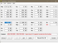
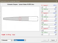
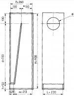
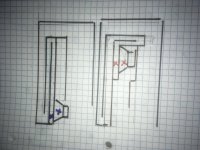
I tried modelling the attached TQWT but the output looks questionable compared to other sims I have seen leading me to think I've entered wrong areas at different parts of the line. Can the good folk spot where I may have gone wrong? Please let me know if this is a question for a different forum of course. I am uncertain of the inductance value of the Triangle T17FL2 driver which may be an issue but the value of .18 mH was on a french catalogue of T/S parameters for the unit. Seems low though.
Hi
I tried modelling the attached TQWT but the output looks questionable compared to other sims I have seen leading me to think I've entered wrong areas at different parts of the line. Can the good folk spot where I may have gone wrong? Please let me know if this is a question for a different forum of course. I am uncertain of the inductance value of the Triangle T17FL2 driver which may be an issue but the value of .18 mH was on a french catalogue of T/S parameters for the unit. Seems low though.
Attachments
This may help... DIY Audio Projects Forum • "Hazard" wide band speaker load
Hi
I tried modelling the attached TQWT but the output looks questionable.....
Greets!
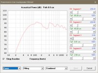
My HR inputs are close to yours except using the base specs and yes, without factoring in driver/vent delay [Chamber/Path] to the listening position [Lp], stuffing impact [Filling] makes for a pretty pathetic looking sim.
That said, this one is barely > Vas, so at minimum a bit small and more so if significant series resistance [Rg] and/or stuffing to smooth it out isn't factored in.
If seated ear height is much different than ~31", consider making the pipe based on yours and use the Wizard to try different net volumes [Vb].
For instance, a T/S max flat alignment is ~100.28 L/44.6 Hz Fb, so ~2.5x larger, tuned slightly lower and depending on the room's acoustics, could be tuned as low as ~0.707x Fs = ~41 Hz.
Some have pushed drivers [much] lower, but power response 'drops like a stone' [excursion increases 4x/octave], so 'caveat emptor' applies big time with a tiny Xmax driver.
GM
Attachments
I see a figure for the inductance though which I wasnt sure about.
I used 1.0, but this spec will probably be less, so has little impact on its HF response.
GM
What might be occurring here to promote bandwidth width more in a SIM?
The blue driver is in the open end of one pipe(small chamber) and low pressure on that side of the cone, yet still very high pressure on the ‘front’ side of the cone(long skinny path).
It’s also firing into the same (not drawn to scale clearly) chamber but from the outside instead of in it, like the red one. The red is in the chamber(pipe) and also the other. Differential pressure is canceled or created in this way.
The red one has a high pressure on both sides of the cone(closed end of two different pipes) and a heck of s motor in this driver that doesn’t care about much... (same driver is used for both, btw).
I’m getting lots of results here. But it’s the actual mechanism or both (maybe more even?) that I’m trying to learn and well enough to use it repeatedly.
Attachments
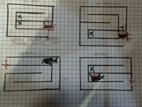
A few examples. We are trying to implement a blend of several sims into one. Pushing paraflex into areas we can’t quite sim.
Motor out for cooling instead of inside the other chamber. The chambers are qw pipes... at 76cm always. But one is fired into from open end(Offset). One has driver inside it. Both fire fire directly into the longer qw path.
Hope I dont confuse you...sorry")
Also, ‘paraflex’ isn’t exactly represented in all of these. They’re mostly missing the series exit and thats ‘path’ in many ways. But thats not in the TH sim application as it is in a paraflex(L45).
Motor out for cooling instead of inside the other chamber. The chambers are qw pipes... at 76cm always. But one is fired into from open end(Offset). One has driver inside it. Both fire fire directly into the longer qw path.
Hope I dont confuse you...sorry
Also, ‘paraflex’ isn’t exactly represented in all of these. They’re mostly missing the series exit and thats ‘path’ in many ways. But thats not in the TH sim application as it is in a paraflex(L45).
Attachments
Last edited:
Didn't quite follow, but the smaller the chamber the higher its BW is shifted. For instance, for a basic BP4 the front chamber is 1/4 the rear's for the flattest BW.
GM
This is a big help! Smoother ‘overlap’ in passband with sizing and even a tapered shape to fit the driver inside the closed end versions .Thx very much GReg
! Any thoughts on the driver in the open end of the one pipe, not actually in it? (11012 posts pic, left vs right configuration )
Last edited:
Will be in the next update.
Thank you, David
Hornresp Update 5090-200824
Hi Everyone,
CHANGE 1
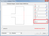
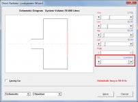
Vented-box enclosure system losses are now taken into account using the QL quality factor parameter. The default value is 7 but the value can be adjusted between 1 and 99 using the slider control in the Chamber section of the Loudspeaker Wizard. If the slider is set to the maximum position, the true lossless model is selected. If the slider is moved to the minimum position, the control is reset to the default value of 7. The QL parameter reverts to the default value of 7 when a different record is selected or a new record is added.
Post #10986 linked below and Attachments 1, 2 and 3 refer.
https://www.diyaudio.com/forums/subwoofers/119854-hornresp-1099.html#post6301419
CHANGE 2
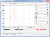
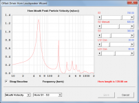
The Loudspeaker Wizard, and the Filter Wizard when activated from the Loudspeaker Wizard, now have a particle velocity chart showing the velocity at the outlet end of the port tube in a bass-reflex system, or at the mouth end of a horn or transmission line system.
Post #10992 linked below and Attachments 4 and 5 refer.
https://www.diyaudio.com/forums/subwoofers/119854-hornresp-1100.html#post6308489
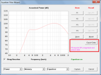
CHANGE 3
When the Filter Wizard is activated from the Loudspeaker Wizard it is now possible to export SPL magnitude and phase data and diaphragm displacement data from the Filter Wizard, taking into account both absorbent filling material and filter settings.
Post #1 linked below and Attachment 6 refer.
https://www.diyaudio.com/forums/subwoofers/358128-export-file-data-hornresponse.html#post6294476
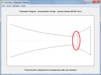
CHANGE 4
A closed-mouth compound horn design can now have a rear chamber positioned between the diaphragm and horn 2.
Post #10980 linked below and Attachment 7 refer.
https://www.diyaudio.com/forums/subwoofers/119854-hornresp-1098.html#post6298203
CHANGE 5
Semi-inductance and FDD advanced driver parameters can now have values less than 0.01. This enables compression driver lumped parameter models to be more accurately specified. The change was suggested by a user simulating compression driver systems.
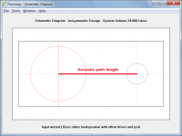
CHANGE 6
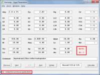
The acoustic path length value for a loudspeaker with offset driver and offset port or offset passive radiator, is now calculated automatically. Attachments 8 and 9 refer.
BUG FIX 1
The minor bug described in Post #38 linked below, has now been fixed.
https://www.diyaudio.com/forums/sub...s-tuned-6th-bandpass-boxes-4.html#post6297077
BUG FIX 2
When the Filter Wizard was opened from the Loudspeaker Wizard and a filter then specified, sometimes after returning to the main chart windows the filter settings were not taken into account in the chart results, even though a status message was displayed indicating that the filter had been applied.
This seemingly intermittent fault would have been present since the Filter Wizard was first added. It has now been fixed.
Stay safe,
David
Hi Everyone,
CHANGE 1
Vented-box enclosure system losses are now taken into account using the QL quality factor parameter. The default value is 7 but the value can be adjusted between 1 and 99 using the slider control in the Chamber section of the Loudspeaker Wizard. If the slider is set to the maximum position, the true lossless model is selected. If the slider is moved to the minimum position, the control is reset to the default value of 7. The QL parameter reverts to the default value of 7 when a different record is selected or a new record is added.
Post #10986 linked below and Attachments 1, 2 and 3 refer.
https://www.diyaudio.com/forums/subwoofers/119854-hornresp-1099.html#post6301419
CHANGE 2
The Loudspeaker Wizard, and the Filter Wizard when activated from the Loudspeaker Wizard, now have a particle velocity chart showing the velocity at the outlet end of the port tube in a bass-reflex system, or at the mouth end of a horn or transmission line system.
Post #10992 linked below and Attachments 4 and 5 refer.
https://www.diyaudio.com/forums/subwoofers/119854-hornresp-1100.html#post6308489
CHANGE 3
When the Filter Wizard is activated from the Loudspeaker Wizard it is now possible to export SPL magnitude and phase data and diaphragm displacement data from the Filter Wizard, taking into account both absorbent filling material and filter settings.
Post #1 linked below and Attachment 6 refer.
https://www.diyaudio.com/forums/subwoofers/358128-export-file-data-hornresponse.html#post6294476
CHANGE 4
A closed-mouth compound horn design can now have a rear chamber positioned between the diaphragm and horn 2.
Post #10980 linked below and Attachment 7 refer.
https://www.diyaudio.com/forums/subwoofers/119854-hornresp-1098.html#post6298203
CHANGE 5
Semi-inductance and FDD advanced driver parameters can now have values less than 0.01. This enables compression driver lumped parameter models to be more accurately specified. The change was suggested by a user simulating compression driver systems.
CHANGE 6
The acoustic path length value for a loudspeaker with offset driver and offset port or offset passive radiator, is now calculated automatically. Attachments 8 and 9 refer.
BUG FIX 1
The minor bug described in Post #38 linked below, has now been fixed.
https://www.diyaudio.com/forums/sub...s-tuned-6th-bandpass-boxes-4.html#post6297077
BUG FIX 2
When the Filter Wizard was opened from the Loudspeaker Wizard and a filter then specified, sometimes after returning to the main chart windows the filter settings were not taken into account in the chart results, even though a status message was displayed indicating that the filter had been applied.
This seemingly intermittent fault would have been present since the Filter Wizard was first added. It has now been fixed.
Stay safe,
David
Attachments

- Home
- Loudspeakers
- Subwoofers
- Hornresp