hi everyone. before asking for help I want to express how much I appreciate all the help in this forum. it's amazing
that said, I've come into possession of some unloaded cerwin vega SL-36B cabinets that I'm going to try to fix up and reuse as a low budget start to a reinforcement system. I've sat through a youtube tutorial on basic sealed enclosures and got moving with the wizard in Hornresp and was very pleased with the results. Now, I think I need a hand learning how to enter a folded enclosure and how to take the measurements for one. I'll gladly provide any information needed if anyone is willing to help since I need to purchase some drivers.
kindly,
- J
IIRC, the HR input data for the SL36 is already on the 'net. It's either here or somewhere like the speakerplans forum. Google might help with that.
Thanks for pointing that out. I did a search and found a screenshot of the parameters that worked for someone else while entering the TS parameters for a loudspeaker that I want to experiment with. I think they simmed for 2 cabs at one time.
I don't understand how to enter "Cir." It's grayed out. The help file calls this the "free space normalised horn mouth circumference in flare cutoff frequency wavelengths."
I'm also unsure what kind of horn to tell hornresp I'm entering per fold. The wizard asks for Bessel ( same person as the filter? ), Conical, Exponential, so on..
My file is "New File"
Old-File — ImgBB
New-File — ImgBB
Last edited:
CHANGE 2
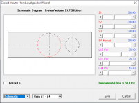
A loudspeaker with an offset driver can now also have an offset port, an offset passive radiator or an offset stub.
Method:
1. Specify at least three segments, select the OD offset driver option and double-click the Cir or Fta label in edit mode to select the Clo closed horn mouth option. Set Vrc, Lrc, Vtc and Atc = 0.
2. Specify an offset port using Ap and Lpt, a passive radiator using Sp, Cmp, Mmp and Rmp, or an offset stub using Ap1 and Lp.
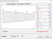
I've finally got a chance to play with this feature, and I'm liking it. I've tried a few driver / vent layouts for a vented system and it seems that, to minimize organ-pipe noise through the vent, the best position for the driver seems to be in the middle of the baffle, and the best position for the vent seems to be about halfway between the driver and the end of the baffle (see diagram). I will have to try a build like this sometime to see if the measurements back up what the sim's saying.
I have one minor recommendation for the feature - have the length of the last segment be dependent on the offset e.g., if L34 represents the offset, then increasing L34 should decrease L23. Adlusting L23 should not impact L34 though. This will allow for changing the port offset without changing the total volume of the sim.
Attachments
I don't understand how to enter "Cir." It's grayed out. The help file calls this the "free space normalised horn mouth circumference in flare cutoff frequency wavelengths."
You don't enter it; it's calculated automatically based on the dimensions of the horn and the radiation solid angle.
I'm also unsure what kind of horn to tell hornresp I'm entering per fold. The wizard asks for Bessel ( same person as the filter? ), Conical, Exponential, so on..
For a horn section made up from two parallel and two conical sides, Parabolic is the best match.
(Bessel: German mathematician Friedrich Bessel developed functions which are used in the design of Bessel filters, and which also appear in the solution of the horn equation for Bessel horns, hence the name.)
I would build the horn in "gramaphone style" with facets that fold back
As previously advised the maximum mouth flare tangent angle will remain at the current Sph and Tra limit of 90 degrees - the horn profile will not fold back.
therefore I was asking for T = 0.4
Not sure how much use it will be, but the lower limit will be set at T = 0.4.
I have one minor recommendation for the feature - have the length of the last segment be dependent on the offset e.g., if L34 represents the offset, then increasing L34 should decrease L23. Adlusting L23 should not impact L34 though.
I will have a look when I get a chance - it probably won't be in the the next update though, which is close to being released.
I need some help with reasonable values for Fr1 in Loudspaker Wizard.
A reasonable value would be one that gives you the best response...
") .
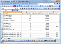
.Some information on airflow resistivity values is attached (not necessarily applicable to loudspeakers).
Attachments
I had expected a rise in response at a quarter wavelength for the cylindrical dogbox.
Have you compared the Hornresp result to that generated by AkAbak?
You don't enter it; it's calculated automatically based on the dimensions of the horn and the radiation solid angle.
For a horn section made up from two parallel and two conical sides, Parabolic is the best match.
(Bessel: German mathematician Friedrich Bessel developed functions which are used in the design of Bessel filters, and which also appear in the solution of the horn equation for Bessel horns, hence the name.)
Thanks! Any idea why my entire upper right side is grayed out? Links to my images are at the end of my recent post.
Have you compared the Hornresp result to that generated by AkAbak?
I will as soon as export to Akabak i supported
I have one minor recommendation for the feature - have the length of the last segment be dependent on the offset e.g., if L34 represents the offset, then increasing L34 should decrease L23. Adlusting L23 should not impact L34 though. This will allow for changing the port offset without changing the total volume of the sim.
Oh, in addition to this, the cross-section of the segment where the offset port is located should be automatically adjusted as well. If it's not, the total volume of the sim will be changed every time the location of the vent is changed.
e.g. for the example given, S3 (like S2) should have an "auto" option.
Attachments
A reasonable value would be one that gives you the best response...
Some information on airflow resistivity values is attached (not necessarily applicable to loudspeakers).
Thanks David!
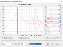
I have increased the damping to 500 in my simulations of different dogbox designs. With damping, the different designs look almost the same, when looking at the power curve. I cannot make a recommendation from these simulations, they all look very similar.
But I suspect that reverberation will be different though. But that I cannot simulate. You will have to include filling into the standard calculation in order to be able to analyze impulse response.
Oh, in addition to this, the cross-section of the segment where the offset port is located should be automatically adjusted as well. If it's not, the total volume of the sim will be changed every time the location of the vent is changed.
e.g. for the example given, S3 (like S2) should have an "auto" option.
Agree!
Thanks! Any idea why my entire upper right side is grayed out? Links to my images are at the end of my recent post.
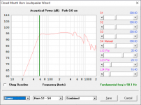
OK see the steps below. They start by your double clicking on the S1 field. Then click on exponential. Then enter the 72 for length. Hit calculate, then save.
Attachments
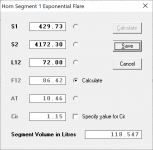
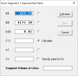
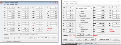
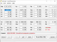
OK see the steps below. They start by your double clicking on the S1 field. Then click on exponential. Then enter the 72 for length. Hit calculate, then save.
Seems to be working. Thanks!
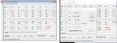
Any idea why my entire upper right side is grayed out?
Text boxes that are disabled when in Edit mode are either outputs not inputs, or are not required for the loudspeaker type being considered.
You will have to include filling into the standard calculation
That's not going to happen
.That's not going to happen
You always says so. But somehow you implement almost all of my suggestions. Just give it some time and it will happen.
Just give it some time and it will happen.
There is no chance - too much work to implement.
- Home
- Loudspeakers
- Subwoofers
- Hornresp