 => David
Pretty sure you have a big white beard
I think you are half right

Nice and useful additions to Hornresp Master McBean.
Thank you very much.
NTI now has been told and explained all about Hornresp.
World loudspeaker software domination soon to follow
Hi Sven,
I thought it already was.
I see from one of your earlier posts that you are an electrical engineer specialising in electroacoustics. I would have thought that electrical engineers should have no problems interpreting the information as currently presented in the Help file.
If you are not sure how to specify a particular loudspeaker system try using the Input Wizard under the Help menu to generate a representative example design, and then adjust the parameter values to suit. Also, it could be worthwhile printing out a paper copy of the Help file and keeping it handy, together with a highlight pen, while working with the program.
Hornresp has evolved over the years into a reasonably versatile and useful tool - like all tools though, it takes a bit of time and effort to learn how to use it correctly. You will find that it is not all that difficult though, once you get started.
All the features available in Hornresp are documented in the Help file as currently written...
Kind regards,
David
but it should be also clearly stated in instructions!
I thought it already was
.Why not state it in instructions the same way you have stated it so clearly here in your response to me?
I see from one of your earlier posts that you are an electrical engineer specialising in electroacoustics. I would have thought that electrical engineers should have no problems interpreting the information as currently presented in the Help file
.If you are not sure how to specify a particular loudspeaker system try using the Input Wizard under the Help menu to generate a representative example design, and then adjust the parameter values to suit. Also, it could be worthwhile printing out a paper copy of the Help file and keeping it handy, together with a highlight pen, while working with the program.
Hornresp has evolved over the years into a reasonably versatile and useful tool - like all tools though, it takes a bit of time and effort to learn how to use it correctly. You will find that it is not all that difficult though, once you get started.
All the features available in Hornresp are documented in the Help file as currently written...
Kind regards,
David
Pretty sure you have a big white beard
Sorry to disappoint - clean-shaven actually
.World loudspeaker software domination soon to follow
That's a worry
.HornResp + DIYSubwoofers.org = Bass Nirvana
Hi Sven,
As a dummy IT guy I worked my way through Bryan Steele's DIY Subwoofers site where he steps you through using Hornresp from sealed (easy) box designs to Bandpass and Tapped Horns (complex). There's a link to each alignment (box type) in the left hand menu list.
This was a revelation for me in that it helped clearly distil the purpose of all those oddly (at first) named fields and all the effects of tweeking ports, path lengths and other settings.
While you are there don't miss his xls workbooks for designing boxes that can actually be modelled and built.
There bass gold in Hornresp and DIYSubwoofers.org!
Enjoy!
This software has instructions that useless (for me), That means NOTHING to me /or any other logical person ...
Hi Sven,
As a dummy IT guy I worked my way through Bryan Steele's DIY Subwoofers site where he steps you through using Hornresp from sealed (easy) box designs to Bandpass and Tapped Horns (complex). There's a link to each alignment (box type) in the left hand menu list.
This was a revelation for me in that it helped clearly distil the purpose of all those oddly (at first) named fields and all the effects of tweeking ports, path lengths and other settings.
While you are there don't miss his xls workbooks for designing boxes that can actually be modelled and built.
There bass gold in Hornresp and DIYSubwoofers.org!
Enjoy!
Last edited:
Hi Giri,
Hornresp calculates the acoustical impedance at a given surface as the complex ratio of effective sound pressure averaged over the surface, to the effective volume velocity through it. The reactive component of the impedance is not calculated in terms of capacitive and inductive elements.
Kind regards,
David
Thanks for the reply, David.
One method suggested by Martin King on his Transmission Line Facebook group, is to reduce the length, keep the volume same and note how much the impedance response changes. If it doesn't change much, the design is more in the realm of reflex than a transmission line. Is it practical to use this logic be used in Hornresp to approximately provide a sense of the capacitative and inductive contribution to a vented design?
Hi Giri,
Sorry, but I am not sure that I understand exactly what it is that you are trying to achieve. In your original post you referred to acoustical impedance, and expressing that in terms of capacitance and inductance. Now you seem to be wanting to use electrical impedance instead, which is something quite different.
I don't know if the following will help you much, but if for example we start with a simple bass-reflex Helmholtz resonator type system, then in lumped-parameter terms, the air in the enclosure when compressed but not accelerated can be considered to be an acoustical compliance (equivalent to an electrical capacitance) and the air in the port tube when accelerated but not compressed can be considered to be an acoustical mass (equivalent to an electrical inductance). As the dimensions of the enclosure and port are altered, the electrical impedance of the system will obviously change as Dr King has indicated, but I am not sure that this will give you much of a sense of the "capacitive" and "inductive" contributions. Even if it did, I am not sure how this information would help you much in the design process.
It is probably easier just to use the Loudspeaker Wizard in Hornresp to adjust your design in real-time until you obtain the performance you want for a given driver. Whether the optimised system at that stage is theoretically acting as a "mass-loaded transmission line" or as a "bass-reflex enclosure" may be of academic interest, but that's about all, I suspect.
Perhaps your questions could be better answered by Dr King? I think that he should be in a position to comment, as your questions are reasonably general ones, and not confined to Hornresp specifically.
Kind regards,
David
Please excuse my newbie ignorance but I understand that the acoustic loading is resistive in horns, inductive in transmission lines, and capacitative in bass reflex and sealed enclosure designs.
This is a simplified generalization. It only applies in certain frequency ranges. For instance, horns are resistive above a certain frequency, but essentially inductive below it. An open straight duct (like a transmission line) is inductive (mass). A closed cavity (closed box) is capacitive (compliance).
But this only applies in the low-frequency range, below the first resonance of the horn, duct or cavity. At higher frequencies the reactance varies between inductive and capacitive, with a resistive part thrown in, depending on losses, which can come from stuffing material and/or radiation. For the approximation to be useful, you need to know the frequency range where it is valid, and this depends on the size and geometry of the system. IIRC, Beranek states that a duct has to be shorter than 1/16 wavelength for it to be approximated by a simple acoustic mass (inductance).
(impedance = resistance + j*reactance, Z = R+jX, where j is the imaginary unit, j = sqrt(-1).)
Is it possible to split reactance data and plot capacitance and inductance in Hornresp?
Capacitive reactance is negative, and inductive reactance is positive, and in this way you can separate inductance and capacitance in the impedance plot in Hornresp.
I think Hornresp only shows the acoustic impedance on the front of the diaphragm.
If it doesn't change much, the design is more in the realm of reflex than a transmission line. Is it practical to use this logic be used in Hornresp to approximately provide a sense of the capacitative and inductive contribution to a vented design?
In terms of programming, this isn't logic, but a subjective evaluation. In order for the program to give you an answer, you need to assign numbers to something: when does it change "much"? >10%? >50%? In what frequency range? What is changing? Frequency of peak(s)? Height of peak(s)?
Another question is why you need this information? What is it used for? Does it help you to tune your design, and if so, in what way?
Hi Giri,
Sorry, but I am not sure that I understand exactly what it is that you are trying to achieve. In your original post you referred to acoustical impedance, and expressing that in terms of capacitance and inductance. Now you seem to be wanting to use electrical impedance instead, which is something quite different.
I don't know if the following will help you much, but if for example we start with a simple bass-reflex Helmholtz resonator type system, then in lumped-parameter terms, the air in the enclosure when compressed but not accelerated can be considered to be an acoustical compliance (equivalent to an electrical capacitance) and the air in the port tube when accelerated but not compressed can be considered to be an acoustical mass (equivalent to an electrical inductance). As the dimensions of the enclosure and port are altered, the electrical impedance of the system will obviously change as Dr King has indicated, but I am not sure that this will give you much of a sense of the "capacitive" and "inductive" contributions. Even if it did, I am not sure how this information would help you much in the design process.
It is probably easier just to use the Loudspeaker Wizard in Hornresp to adjust your design in real-time until you obtain the performance you want for a given driver. Whether the optimised system at that stage is theoretically acting as a "mass-loaded transmission line" or as a "bass-reflex enclosure" may be of academic interest, but that's about all, I suspect.
Perhaps your questions could be better answered by Dr King? I think that he should be in a position to comment, as your questions are reasonably general ones, and not confined to Hornresp specifically.
Kind regards,
David
Hello, David. I'm quite a newbie. I understand that a TL is more fault tolerant to design inaccuracies than a bass reflex. So, I was concerned that as I tweak an MLTL, I'd eventually end up with a design that's more bass reflex than a TL. So, I was wondering if there's a way I can know by what extant a TL design has acquired bass reflex characteristics, as I try to reduce the line length. I'm possibly out of my depth.
This is a simplified generalization. It only applies in certain frequency ranges. For instance, horns are resistive above a certain frequency, but essentially inductive below it. An open straight duct (like a transmission line) is inductive (mass). A closed cavity (closed box) is capacitive (compliance).
But this only applies in the low-frequency range, below the first resonance of the horn, duct or cavity. At higher frequencies the reactance varies between inductive and capacitive, with a resistive part thrown in, depending on losses, which can come from stuffing material and/or radiation. For the approximation to be useful, you need to know the frequency range where it is valid, and this depends on the size and geometry of the system. IIRC, Beranek states that a duct has to be shorter than 1/16 wavelength for it to be approximated by a simple acoustic mass (inductance).
(impedance = resistance + j*reactance, Z = R+jX, where j is the imaginary unit, j = sqrt(-1).)
Capacitive reactance is negative, and inductive reactance is positive, and in this way you can separate inductance and capacitance in the impedance plot in Hornresp.
I think Hornresp only shows the acoustic impedance on the front of the diaphragm.
In terms of programming, this isn't logic, but a subjective evaluation. In order for the program to give you an answer, you need to assign numbers to something: when does it change "much"? >10%? >50%? In what frequency range? What is changing? Frequency of peak(s)? Height of peak(s)?
Another question is why you need this information? What is it used for? Does it help you to tune your design, and if so, in what way?
Thanks for the explanation. That helps a lot. My primary concern is that my simulated design stay an inductive TL at resonance, rather than a bass reflex that's more sensitive to design variations.
Capacitive reactance is negative, and inductive reactance is positive, and in this way you can separate inductance and capacitance in the impedance plot in Hornresp.
Just to clarify, it is necessary to export the electrical input impedance magnitude (Ze) and phase (ZePhase) data before the resistive (R) and reactive (X) components can be extracted.
R = Ze * Cos(ZePhase)
X = Ze * Sin(ZePhase)
Attachments
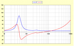
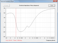
Further to my post above, if the numerical values of the inductive and capacitive components of the reactance are not required and only the frequencies at which they occur are of interest, then this information can be determined directly from the electrical impedance phase response. If the phase is positive, the reactance will be inductive (ie. below 46 Hz and above 600 Hz in my previous design example).
Attachments
Acoustic capacitance and inductance etc.
Hello David and Kolberk,
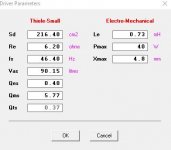
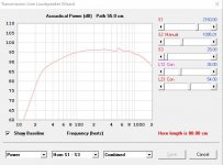
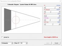
Just for reference, this is the simulation that made me wonder about capacitance and inductance at the tuning frequency. Started with a normal TL but as I tweaked the design, I had to keep increasing the S1 to compensate for the lower Qts. What I ended up with was a stunningly short line length, with decent frequency response. But obviously, its TL character is now questionable.
Thank you
Hello David and Kolberk,
Just for reference, this is the simulation that made me wonder about capacitance and inductance at the tuning frequency. Started with a normal TL but as I tweaked the design, I had to keep increasing the S1 to compensate for the lower Qts. What I ended up with was a stunningly short line length, with decent frequency response. But obviously, its TL character is now questionable.
Thank you
Attachments
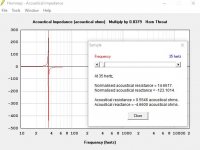
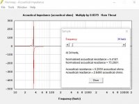
Further to my post above, if the numerical values of the inductive and capacitive components of the reactance are not required and only the frequencies at which they occur are of interest, then this information can be determined directly from the electrical impedance phase response. If the phase is positive, the reactance will be inductive (ie. below 46 Hz and above 600 Hz in my previous design example).
Exactly what I needed. Thanks.
- Home
- Loudspeakers
- Subwoofers
- Hornresp