it seems the problem was with the Drivers folder - I was not able to delete it
Hi pelanj,
That is very strange indeed. In my case, I can delete the Drivers folder even when Hornresp is running.
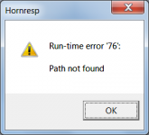
If I then attempt to paste a driver from the now non-existent database folder into a Hornresp record, I get the attached fatal error, as expected.
If I then re-open Hornresp the Drivers folder is automatically re-created containing the default driver file.
Kind regards,
David
Attachments
Hi
If this happens again and you want to track down what is occupying the file, you could use "isusedby" from mst Soft. Its a small programm which checks if a file is opened by another application and tells you which one it is. It should be started in admin mode (right mouse on the EXE: "open as administrator").
Opening the task manager then allows you to force shut down this process.
mst IsUsedBy 2.0.8.94 wird heruntergeladen | Freeware.de
This is a german download link, but "download" works easily. The program is all over the web, I assume it´s not developed any further - didn't check for ages - worked fine for me in the past to find out if a process is blocking files.
Glad a restart solved your problem.it seems the problem was with the Drivers folder - I was not able to delete it - it reported it was used by some application - maybe an incorrectly terminated Hornresp session?
If this happens again and you want to track down what is occupying the file, you could use "isusedby" from mst Soft. Its a small programm which checks if a file is opened by another application and tells you which one it is. It should be started in admin mode (right mouse on the EXE: "open as administrator").
Opening the task manager then allows you to force shut down this process.
mst IsUsedBy 2.0.8.94 wird heruntergeladen | Freeware.de
This is a german download link, but "download" works easily. The program is all over the web, I assume it´s not developed any further - didn't check for ages - worked fine for me in the past to find out if a process is blocking files.
Hornresp Update 5040-190906
Hi Everyone,
BUG FIX 1
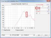
If a H-frame open baffle loudspeaker system was specified with S1 > Sd, the Loudspeaker Wizard then opened, the Power response chart selected, the L12 slider set to 0.10 to specify a U-frame, and the B key then pressed to restore the original L12 slider value, the restored response was different to the original and the L12 slider caption changed from 'L12 Side 1' to 'L12' plus the flare type - see Attachment 1. This has now been fixed.
BUG FIX 2
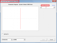
If an unbaffled driver or flat open baffle loudspeaker system was specified and the Loudspeaker Wizard then opened, the wizard caption was incorrectly shown as 'Compound Horn Loudspeaker Wizard' - see Attachment 2. This has now been fixed.
Kind regards,
David
Hi Everyone,
BUG FIX 1
If a H-frame open baffle loudspeaker system was specified with S1 > Sd, the Loudspeaker Wizard then opened, the Power response chart selected, the L12 slider set to 0.10 to specify a U-frame, and the B key then pressed to restore the original L12 slider value, the restored response was different to the original and the L12 slider caption changed from 'L12 Side 1' to 'L12' plus the flare type - see Attachment 1. This has now been fixed.
BUG FIX 2
If an unbaffled driver or flat open baffle loudspeaker system was specified and the Loudspeaker Wizard then opened, the wizard caption was incorrectly shown as 'Compound Horn Loudspeaker Wizard' - see Attachment 2. This has now been fixed.
Kind regards,
David
Attachments
Thanks David!
Hi Mark,
Thanks for the thanks, but the person to really thank in this case is 'bolserst', for making his "acoustic centre" dipole model available for use in Hornresp. His very elegant model produces results that have proven to be most accurate when compared against the measured performance of actual "doublet source" loudspeakers.
Kind regards,
David
Well then. Thanks Stephen and David. A team effort!
A team effort!
I can't speak for 'bolserst' but it was certainly a very interesting and productive collaboration as far as I am concerned
") .
.Hi Michael,
It was Rudolf's work to simulate H-dipol and Ripol in the AJ-Horn programme that got me interested in what Hornresp could do. In fact with the use of the Compound Horn model it is very easy to set up these models. And I think that the results are valid. H-dipol simus I have compared to MJK's models and the difference is very small.
Here is a Ripole example, which is the same as Rudolf use in his paper in the Download section on his Web: Offene Schallwand (OB) . I think that the pictures tell the story, combined response is calculated with 37 cm difference as in Rudolf's example.
An externally hosted image should be here but it was not working when we last tested it.
An externally hosted image should be here but it was not working when we last tested it.
The Hornresp results are a bit different from Rudolf's and I am no Ripol-expert, so it would be nice if he could comment on them.
/Erling
Pictures and instructions are gone.
Any chance of a repost?
Please can I ask if there is a new way to accurately model a "Ripole" open baffle woofer in Hornresp? If so please attach the Hornresp file.

Does anyone have a sample they can show?
Does anyone have a sample they can show?
Hi DaveFred,
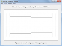
It seems that people may be reluctant to have a go, so here's my attempt...
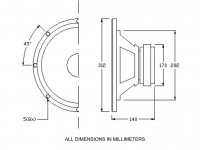
.I have used the dimensions shown in your schematic, and two of the Hornresp default drivers connected in parallel. The model is obviously not perfect (drivers not offset) but it should give a reasonable indication of the expected performance.
Kind regards,
David
PS - If anyone has a more accurate Hornresp ripole model could you please post it. I won't be offended in the slightest
.Attachments
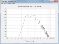
here's my attempt...
I should have specified a non-zero acoustical path length. Somewhere around 50 cm seems about right.
I should have specified a non-zero acoustical path length. Somewhere around 50 cm seems about right.
Hello David,
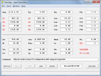
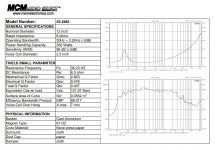
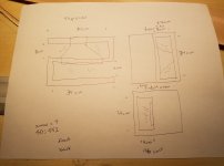
I made a child's drawing of a ripole with I think all the proper dimensions and here is all the data I could muster,
Here are I think all the relevant parameters as measured by me after four hours of break in,
F(s) = 41.72 Hz
Q(ts) = 0.6957
V(as) = 90.28 liters
SPL = 90.79 dB SPL 1W/1m
R(e) = 6.638 Ohms
Q(es) = 0.8446
Piston diameter = 260.4mm
SPL = 91.6 dB SPL 2.83 Vrms
C(ms) = 0.227 mm/N
L(e) = 0.6765 mH at 10kHz
Q(ms) = 3.947
BL = 11.5
n(0) = 0.7402%
M(ms) = 64.16 grams
Xmax = 7 mm
SD = 552 cm^2
Anyone care to take a stab at it?
Thank you,
David.
Attachments
Anyone care to take a stab at it?
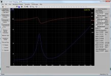
Hi David,
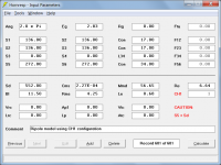
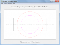
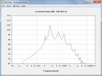
The attachments show my attempt.
CH1 rather than CH has been used so that the front side offset driver position is taken into account. Unfortunately this does not apply to the rear side, so that the overall results are somewhat compromised. An acoustic path length of 40 cm has been assumed.
If you are serious about accurately simulating a ripole then you should really be using AkAbak, not Hornresp
.Kind regards,
David
Attachments
Is it important to have 30 uf or15uf cap to protect a Compression driver when using an active system? When using a tube amps.
Hi multi,
I don't have an answer to your question but someone on the Multi-Way Loudspeakers forum may know. Perhaps it might be worth re-posting your question there?
This thread is mainly about subwoofers and Hornresp
.Kind regards,
David
Is it important to have 30 uf or15uf cap to protect a Compression driver when using an active system? When using a tube amps.
Thanks
It is a wise thing to have a passive protection network on an expensive driver. The correct values need to be calculated for the driver characteristics.
Perhaps I can be of assistance.
Tube amps are characterised by having transformers in the output stage, in order to adapt the tubes inherent high impedance to the loudspeakers inherent low impedance.
Transformers can not pass a DC voltage, which I am sure is your concern.
Thus, in such case, an isolating capacitor should not be necessary.
Single-ended transistor amplifiers already have an isolating capacitor in the output, so in this case too an extra capacitor should not be necessary.
Push-Pull transistor amplifiers however, deserves some attention:
Two output devices are suspended between the pos. and neg. supply rails respectively. If ONE of the devices (or assosiated circuitry) decides to blow, it is almost certain that the output will smack out to one or the other supply rail, depending on a short or an open circuit.
With such amp. it could be an idea to include an isolating capacitor indeed.
Strangely, one sometimes see mini-fuses on-board the PCB in each supply of the amplifier !
So a 50 cent fuse, deciding to blow, will fry a 500$ loudspeaker.
Ironically, class D amps actually do switch between supply rails, though very fast. An isolating/smoothing inductor keep things ample for loudspeaker use.
However, the class D amps I have worked with all had a high level and high frequency carrier superimposed to the output.
So a large voice coil inductance is definitely necessary to quench this and dessipate a few watts.
A woofers coil is probably OK for this, but a fine tweeter ?
I would´nt use class D amps for active filtering, except for woofers which I already do.
Perhaps I can be of assistance.
Tube amps are characterised by having transformers in the output stage, in order to adapt the tubes inherent high impedance to the loudspeakers inherent low impedance.
Transformers can not pass a DC voltage, which I am sure is your concern.
Thus, in such case, an isolating capacitor should not be necessary.
Single-ended transistor amplifiers already have an isolating capacitor in the output, so in this case too an extra capacitor should not be necessary.
Push-Pull transistor amplifiers however, deserves some attention:
Two output devices are suspended between the pos. and neg. supply rails respectively. If ONE of the devices (or assosiated circuitry) decides to blow, it is almost certain that the output will smack out to one or the other supply rail, depending on a short or an open circuit.
With such amp. it could be an idea to include an isolating capacitor indeed.
Strangely, one sometimes see mini-fuses on-board the PCB in each supply of the amplifier !
So a 50 cent fuse, deciding to blow, will fry a 500$ loudspeaker.
Ironically, class D amps actually do switch between supply rails, though very fast. An isolating/smoothing inductor keep things ample for loudspeaker use.
However, the class D amps I have worked with all had a high level and high frequency carrier superimposed to the output.
So a large voice coil inductance is definitely necessary to quench this and dessipate a few watts.
A woofers coil is probably OK for this, but a fine tweeter ?
I would´nt use class D amps for active filtering, except for woofers which I already do.
There is also a possibility that he is placing a capacitor into the signal path in case his setting son the electronic crossover are accidentally incorrect.
when my audio inovations 500 failed (anodes glowing red hot) the o/p transformer protected my speakers.With dc coupled solid state speakers would almost certainly burn.
BTW :>I once (over 30 years ago)built a copy of the B&W APOC circuit from the patent. My old B&W had tweeter protecion fuse (high resistance) hence I built the APOC.
BTW :>I once (over 30 years ago)built a copy of the B&W APOC circuit from the patent. My old B&W had tweeter protecion fuse (high resistance) hence I built the APOC.
- Home
- Loudspeakers
- Subwoofers
- Hornresp