Hi Jim,
Cir is the free space normalised horn mouth circumference in flare cutoff frequency wavelengths.
Using your example:
Ang = 0.5 x Pi (eighth space)
S2 = 9000.00
F12= 38.02
Free space normalised horn mouth area = 9000 * 8 = 72000 cm^2
Free space normalised horn mouth circumference = 951.20 cm
Flare cutoff frequency wavelength = 34400 / 38.02 = 904.79 cm
Cir = 951.20 / 904.79 = 1.05....
David, thanks for pointing out the obvious! Once I saw your response, it made sense that the effective mouth area is larger due to the 0.5 x pi loading.
Jim.
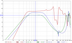
The attached image is a comparison of the Dayton PA310 (rated 96.1dB/2.83V/1M) simmed in a (1) 65 liter 48 Hz MLTL, (2) 65 liter 4th order B and (3) 46 L 4th order BP.
The passband SPL differences between the MLTL and the two BP enclosures is pretty significant (4.3dB) in the first instance, where the systems are the same box volume.
I'm just wondering if this is expected behaviour. I was expecting a difference, but not that big.
The passband SPL differences between the MLTL and the two BP enclosures is pretty significant (4.3dB) in the first instance, where the systems are the same box volume.
I'm just wondering if this is expected behaviour. I was expecting a difference, but not that big.
Attachments
you might also consider mwmkravchenco's comment post9121
Hi Erik,
Mark's suggestion would require even more work to implement
") .
.Your originally-requested feature (the ability to see the combined gain of specified Active and Equaliser filters) will be included in the next release.
Kind regards,
David
Trade-off is high pass slope => higher group delay. Try simulate the same curve with 6th parrallel bandpass with same volume to get same efficiency. Around 48 +16 liters as starting point.The attached image is a comparison of the Dayton PA310 (rated 96.1dB/2.83V/1M) simmed in a (1) 65 liter 48 Hz MLTL, (2) 65 liter 4th order B and (3) 46 L 4th order BP.
The passband SPL differences between the MLTL and the two BP enclosures is pretty significant (4.3dB) in the first instance, where the systems are the same box volume.
I'm just wondering if this is expected behaviour. I was expecting a difference, but not that big.
gr8Hi Erik,
Mark's suggestion would require even more work to implement
Your originally-requested feature (the ability to see the combined gain of specified Active and Equaliser filters) will be included in the next release.
Kind regards,
David
tnx a bunch

Model a Horn Driver Without Horn
Hi,
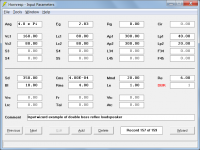
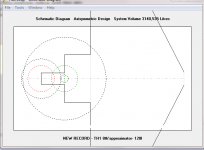
I would like to model a bass horn driver without seeing the effects of the limited horn mouth size if possible.
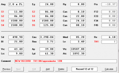
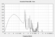
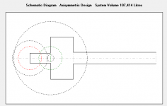
I tried setting the horn mouth size to 99,999 and length appropriate as in the attachment below, but there is still significant ripple that would hide the effects of the driver ripple. I would like a way to isolate the driver ripple.
*****EDIT*****
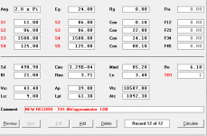
I found out that setting Ang to zero, and Exp to 1000 or higher allows me to model just the effect of the driver.
Thanks, Jim
Hi,
I would like to model a bass horn driver without seeing the effects of the limited horn mouth size if possible.
I tried setting the horn mouth size to 99,999 and length appropriate as in the attachment below, but there is still significant ripple that would hide the effects of the driver ripple. I would like a way to isolate the driver ripple.
*****EDIT*****
I found out that setting Ang to zero, and Exp to 1000 or higher allows me to model just the effect of the driver.
Thanks, Jim
Attachments
Last edited:
If I understand the question, just input the driver's specs to get a true enough infinite baffle [IB], i.e. 2pi space.
GM
Thanks GM, I found "Direct Radiator in an Open Baffle" in the help file after your nudge, and followed the directions to set things up.
I was expecting to see more resonance and SPL ripples from modeling the driver in this space, but the output is more damped than anticipated.
Jim.
Thanks GM, I found "Direct Radiator in an Open Baffle" in the help file after your nudge, and followed the directions to set things up.
Wouldn't the "Direct Radiator in an Infinite Baffle" model be better, as originally suggested by GM?
Hornresp Update 4900-190208
Hi Everyone,
CHANGE 1 - Requested by Damien (papasteack)
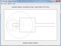
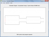
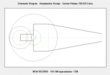
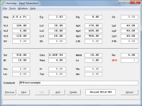
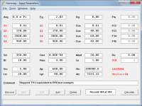
Double-clicking on any segment area label in edit mode allows different cross-sectional areas to be specified at the common boundary between two horn segments in a multiple-segment horn. The mouth area of the first segment does not necessarily have to be the same as the throat area of the second segment. This will result in a step transition at the common boundary. All horn segment area labels are shown in red when stepped segments are specified.
When stepped segments are specified it is not possible to use the Loudspeaker or Multiple Entry Horn Wizards, export schematic diagram horn data, print the schematic diagram, export an AkAbak script or open the current record in the Wavefront Simulator. These limitations were imposed to reduce to an acceptable level the amount of work required to implement the change.
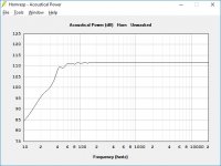
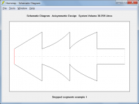
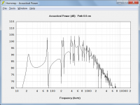
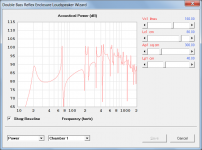
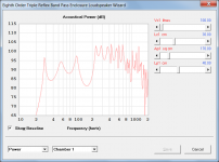
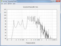
Attachment 1 shows the power response for the double bass reflex system specified in Attachment 3. Attachment 2 shows the power response for the same system, constructed using four stepped segments, as specified in Attachments 4 and 5. The results are slightly different because the DBR Wizard takes port tube end corrections into account, whereas the system using stepped segments does not. Attachments 6 and 7 show other examples of how stepped segments can be used.
CHANGE 2 - Requested by USRFobiwan
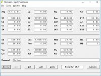
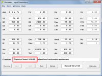
Each time a driver is pasted from the driver database, the name given by the user to the currently-selected driver is automatically inserted in front of the existing comment, as shown in Attachment 8.
CHANGE 3 - Requested by Erik (epa)
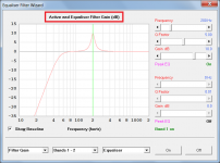
The Filter Wizard now displays combined active and equaliser filter gain, as shown in Attachment 9. While not requested, combined active and equaliser filter phase response and combined active and equaliser filter group delay can now also be displayed.
BUG FIX
The bug reported by Brian in Post #9124 has been fixed. The same bug had also been affecting the results for parallel BP6 systems.
NOTE
This update has required more than one hundred coding changes to various parts of the program. I suspect that there may still be even further changes required that have not yet been picked up. Due to the extent of the changes so far, it is likely that new bugs may have been inadvertently introduced. Could you please report any that you find.
Kind regards,
David
Hi Everyone,
CHANGE 1 - Requested by Damien (papasteack)
Double-clicking on any segment area label in edit mode allows different cross-sectional areas to be specified at the common boundary between two horn segments in a multiple-segment horn. The mouth area of the first segment does not necessarily have to be the same as the throat area of the second segment. This will result in a step transition at the common boundary. All horn segment area labels are shown in red when stepped segments are specified.
When stepped segments are specified it is not possible to use the Loudspeaker or Multiple Entry Horn Wizards, export schematic diagram horn data, print the schematic diagram, export an AkAbak script or open the current record in the Wavefront Simulator. These limitations were imposed to reduce to an acceptable level the amount of work required to implement the change.
Attachment 1 shows the power response for the double bass reflex system specified in Attachment 3. Attachment 2 shows the power response for the same system, constructed using four stepped segments, as specified in Attachments 4 and 5. The results are slightly different because the DBR Wizard takes port tube end corrections into account, whereas the system using stepped segments does not. Attachments 6 and 7 show other examples of how stepped segments can be used.
CHANGE 2 - Requested by USRFobiwan
Each time a driver is pasted from the driver database, the name given by the user to the currently-selected driver is automatically inserted in front of the existing comment, as shown in Attachment 8.
CHANGE 3 - Requested by Erik (epa)
The Filter Wizard now displays combined active and equaliser filter gain, as shown in Attachment 9. While not requested, combined active and equaliser filter phase response and combined active and equaliser filter group delay can now also be displayed.
BUG FIX
The bug reported by Brian in Post #9124 has been fixed. The same bug had also been affecting the results for parallel BP6 systems.
NOTE
This update has required more than one hundred coding changes to various parts of the program. I suspect that there may still be even further changes required that have not yet been picked up. Due to the extent of the changes so far, it is likely that new bugs may have been inadvertently introduced. Could you please report any that you find.
Kind regards,
David
Attachments

This is a really awesome update and lot of hope for next requests ! 
Thank you very much David.
I've played with it for a hour, and it's really interesting.
I didn't managed to reproduce the same result as with 8th order wizard, using stepped segment TH1 with back and front chamber + throat adapter. But I'll try to figure if there's a problem simming with Akabak too when i'll have more time.
EDIT : Bug repport ...I got a non working example bellow with two sim.
Capture 1, 2, 3 are the first sim. Capture 4, 5, 6 are the second sim with only S4 of last segment changed.
The change is taken in account in shematic, but don't change anything to the result. Sorry ...
Last capture is just for fun with this S4 of last segment at 99999,00. It gives the same freq response as the two others sims ^^
Damien
Attachments

Last edited:
Just to help about itBug repport ...

It seems to only happens with TH/TH1 arrangement.
Changes in left column of S2/S3/S4 areas aren't taken in account in calcul for TH/TH1 arrangements , even if shown right in schematic.
Damien
It seems to only happens with TH/TH1 arrangement.
Changes in left column of S2/S3/S4 areas aren't taken in account in calcul for TH/TH1 arrangements , even if shown right in schematic.
Hi Damien,
Many thanks for the prompt feedback. I have found the problem - the only trick now, is to work out how to get around it
.I will keep you posted on progress.
(Incidentally, once I clear all the bugs, I want to get back to further investigating the possibility of modifying the Loudspeaker Wizard to accept stepped cylindrical horn segments only. I think that this should be a lot easier to do than having to also allow for Con, Exp and Par flare stepped segments).
Kind regards,
David
Last edited:
I didn't managed to reproduce the same result as with 8th order wizard, using stepped segment TH1 with back and front chamber + throat adapter.
Hi Damien,
Due to the bug you found the TH1 stepped segment results are not correct. Could you please post the input parameters for your 8th order wizard example and those for your equivalent TH1 model, so that I can do a "sanity check" and compare the two after the bug is hopefully cleared. The error you show in the schematic diagram (exceeding the boundary limits) will also be fixed.
Kind regards,
David
(Incidentally, once I clear all the bugs, I want to get back to further investigating the possibility of modifying the Loudspeaker Wizard to accept stepped cylindrical horn segments only. I think that this should be a lot easier to do than having to also allow for Con, Exp and Par flare stepped segments).
Hi David,
Are cylindrical segments the same as conical?
Please don't ditch parabolic, most of the stuff I build is from flat boards with 2 parallel walls.
Could you please post the input parameters for your 8th order wizard example and those for your equivalent TH1 model, so that I can do a "sanity check" and compare the two after the bug is hopefully cleared.
Hi Damien,
No need for you to provide the test examples - I have come up with my own
.As for my earlier DBR test, the results are slightly different due to the BP8 Wizard taking port tube end corrections into account, whereas the TH1 model does not. If the end corrections are removed, as I have done for my comparison test, the results become identical, which is very reassuring indeed. It means that the BP8 and stepped TH1 models, which are coded quite differently, must both be working correctly
.Kind regards,
David
Attachments
- Home
- Loudspeakers
- Subwoofers
- Hornresp