Congratulations!!... my first soon was just burn ...
Thanks again David!
And not wanting to badger, but would you consider making this a standard option from the edit screen, i.e. the ability to easily select both a vented enclosure plus filling and/or acoustic lining?
For any vented full range speaker, some kind of porous material in the box is almost mandatory, so it would make sense for it to be easy to calculate...
Andreas
haven't being able to work on simulation lately because my first soon was just burn and he is consuming a lot of my time.
Family is most important!
Hi David,
I'm back at it here, this time trying to model a Synergy-type horn, mostly to continue getting the hang of the software.
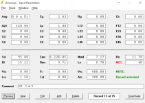
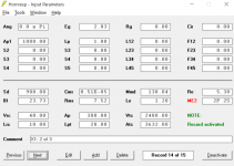
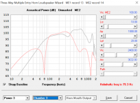
I've entered all the relevant driver parameters in ME1 and ME2, then activated both records and opened the Multiple Entry Horn Wizard from the 3rd record.
When I model each of ME1 and ME2 individually (as separate stand-alone records), I get approximately the results I seek, but the Wizard nevertheless seems to give me a big mess.
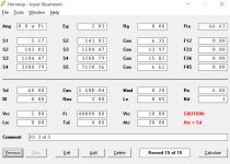
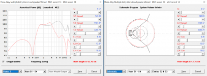
Attached are screenshots of each individual record, plus two screenshots of the Wizard (schematic and power views).
Any idea what I'm doing wrong?
Thanks again")
Also, do you accept donations for all your hard work somewhere?!
Cheers,
Andreas
I'm back at it here, this time trying to model a Synergy-type horn, mostly to continue getting the hang of the software.
I've entered all the relevant driver parameters in ME1 and ME2, then activated both records and opened the Multiple Entry Horn Wizard from the 3rd record.
When I model each of ME1 and ME2 individually (as separate stand-alone records), I get approximately the results I seek, but the Wizard nevertheless seems to give me a big mess.
Attached are screenshots of each individual record, plus two screenshots of the Wizard (schematic and power views).
Any idea what I'm doing wrong?
Thanks again
Also, do you accept donations for all your hard work somewhere?!
Cheers,
Andreas
Attachments
Hi Andreas,
The way that Hornresp has evolved, it would be extremely difficult to now seamlessly integrate the requested feature - it's not going to happen.
Suggest you just use the 'resonances masked' option, the overall effect will be the same.
Kind regards,
David
would you consider making this a standard option from the edit screen, i.e. the ability to easily select both a vented enclosure plus filling and/or acoustic lining?
The way that Hornresp has evolved, it would be extremely difficult to now seamlessly integrate the requested feature - it's not going to happen
.For any vented full range speaker, some kind of porous material in the box is almost mandatory, so it would make sense for it to be easy to calculate...
Suggest you just use the 'resonances masked' option, the overall effect will be the same.
Kind regards,
David
Hi Andreas,
In your Nd record (3 of 3) you have specified an infinite length horn. Change Ang to 2.0 x Pi or 4.0 x Pi.
In the wizard you are looking at the horn-side power response of ME2 only. Select Total Power and Combined Output to see the overall system performance.
No.
Kind regards,
David
Any idea what I'm doing wrong?
In your Nd record (3 of 3) you have specified an infinite length horn. Change Ang to 2.0 x Pi or 4.0 x Pi.
In the wizard you are looking at the horn-side power response of ME2 only. Select Total Power and Combined Output to see the overall system performance.
Also, do you accept donations for all your hard work somewhere?!
No
.Kind regards,
David
Thanks again
I've now changed Ang in my ND record to 4Pi. It remains zero in both ME records though - is that as it should be?
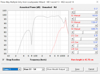
Back in the Multiple Entry Horn Wizard now, I'm trying to experiment with adding bass reflex ports to the bass woofers.
Am I going about it right? I can see a null in the woofer output at the tuning frequency in the frequency response, but I'm not sure how to see the output from the port or the combined output from the port and the woofers. Is there some way to do this?
Cheers,
A
I've now changed Ang in my ND record to 4Pi. It remains zero in both ME records though - is that as it should be?
Back in the Multiple Entry Horn Wizard now, I'm trying to experiment with adding bass reflex ports to the bass woofers.
Am I going about it right? I can see a null in the woofer output at the tuning frequency in the frequency response, but I'm not sure how to see the output from the port or the combined output from the port and the woofers. Is there some way to do this?
Cheers,
A
Attachments
Hi Andreas,
The Ang parameter is not applicable to ME records, which is why it is set to zero and cannot be changed by the user.
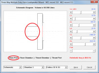
1. Mask the outputs from the Nd compression driver and ME1 drivers as follows:
1.1. Set the Nd and ME1 Eg values to 0.01 (when the Eg slider has the focus, key in 0.01 and press Enter to set the slider value) - see Attachment 1.
1.2. Set ME1 Ap1 and Lp values to 0.01 - see Attachment 2.
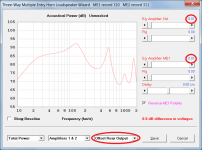
2. To see the output from the port, select Total Power and Offset Rear Output - see Attachment 1.
3. To see the combined output from the port and woofers, select Total Power and Combined Output - see Attachment 2.
Kind regards,
David
I've now changed Ang in my ND record to 4Pi. It remains zero in both ME records though - is that as it should be?
The Ang parameter is not applicable to ME records, which is why it is set to zero and cannot be changed by the user.
I can see a null in the woofer output at the tuning frequency in the frequency response, but I'm not sure how to see the output from the port or the combined output from the port and the woofers. Is there some way to do this?
1. Mask the outputs from the Nd compression driver and ME1 drivers as follows:
1.1. Set the Nd and ME1 Eg values to 0.01 (when the Eg slider has the focus, key in 0.01 and press Enter to set the slider value) - see Attachment 1.
1.2. Set ME1 Ap1 and Lp values to 0.01 - see Attachment 2.
2. To see the output from the port, select Total Power and Offset Rear Output - see Attachment 1.
3. To see the combined output from the port and woofers, select Total Power and Combined Output - see Attachment 2.
Kind regards,
David
Attachments
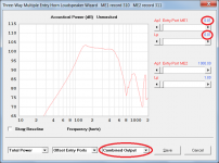
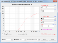
And regarding the compression driver output, what would the reason be for the massive difference between the modelled outputs in the Wizard and when calculated?
Hi Andreas,
You need to remove the effect of the ME1 and ME2 drivers and associated chambers by setting the ME1 and ME2 Eg and Ap1 values to 0.01.
As you have discovered, the interactions between the drivers in a Synergy-type loudspeaker system are extremely complex
.Kind regards,
David
Attachments
Thanks again David. I do realise that the interactions are very complex, but what the sim seems to be doing is modelling the ME1 and ME2 ports as two single large ports (not 8+ small corner ports), which would result in the gross modelled interference - or so I hope! Is that a correct assumption?
A
A
Maybe the answer to this is buried somewhere in the previous 800+ pages of this and I missed it... but, here goes....
I'm having one of those moments where the thought of common sense real-world application, & simulation results are causing the misfiring of too many synapses to ignore.
Then again, maybe I just don't have a deep enough understanding of the physics involved & this is actually true. Wouldn't be the 1st time for that either.
In a nutshell, the basic question is.... Does location in space (half, quarter, eighth, etc) actually effect the physical action/loading of the driver in the box?
If I take a box, that's performing perfectly (physically & electrically speaking - ignoring frequency response for the moment) while sitting in a corner of a room (0.5xPI), would that change (and if so, why) if I did nothing else but took that box out of the corner & hung it in the middle of space (4.0xPI)?
While messing with simulations on various drivers as replacements for an old bass guitar horn-type cab, I was well into trying various drivers when I noticed that I had forgotten to change Ang from the default 0.5 to 2.0. After making that change, I noticed that for the same wattage input the driver now hit it's X-max limit 5Hz higher in half-space than it had in eighth-space. (60Hz vs 55Hz)
Does that happen in the real-world?
Maybe I'm splitting hairs here. 5Hz in the grand scheme of things as far as this particular situation goes isn't a huge deal. & maybe this is just one of those situations where a simulation & real-world application are going to differ without the sim getting overly complex in its calculations. But, it stuck my curiosity nerve too much to ignore, so I have to ask.
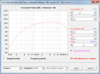
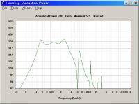
As an illustration.... in the two attached screen-shots, both are the same driver, same box, both being fed the same power... only difference is that one is in eighth-space (0.5xPI) while the other is in free-space (4.0xPI). Notice that the one in free-space is hitting its X-max between 50 & 60Hz.
Nothing changed, just the box moved from a corner to being hung in the middle of space.
I'm having one of those moments where the thought of common sense real-world application, & simulation results are causing the misfiring of too many synapses to ignore.
Then again, maybe I just don't have a deep enough understanding of the physics involved & this is actually true. Wouldn't be the 1st time for that either.
In a nutshell, the basic question is.... Does location in space (half, quarter, eighth, etc) actually effect the physical action/loading of the driver in the box?
If I take a box, that's performing perfectly (physically & electrically speaking - ignoring frequency response for the moment) while sitting in a corner of a room (0.5xPI), would that change (and if so, why) if I did nothing else but took that box out of the corner & hung it in the middle of space (4.0xPI)?
While messing with simulations on various drivers as replacements for an old bass guitar horn-type cab, I was well into trying various drivers when I noticed that I had forgotten to change Ang from the default 0.5 to 2.0. After making that change, I noticed that for the same wattage input the driver now hit it's X-max limit 5Hz higher in half-space than it had in eighth-space. (60Hz vs 55Hz)
Does that happen in the real-world?
Maybe I'm splitting hairs here. 5Hz in the grand scheme of things as far as this particular situation goes isn't a huge deal. & maybe this is just one of those situations where a simulation & real-world application are going to differ without the sim getting overly complex in its calculations. But, it stuck my curiosity nerve too much to ignore, so I have to ask.
As an illustration.... in the two attached screen-shots, both are the same driver, same box, both being fed the same power... only difference is that one is in eighth-space (0.5xPI) while the other is in free-space (4.0xPI). Notice that the one in free-space is hitting its X-max between 50 & 60Hz.
Nothing changed, just the box moved from a corner to being hung in the middle of space.
Attachments

what the sim seems to be doing is modelling the ME1 and ME2 ports as two single large ports (not 8+ small corner ports), which would result in the gross modelled interference
Hi Andreas,
As the schematic diagrams show, the multiple components of ME1 are modelled as a single composite driver / chamber / port assembly. ME2 is treated the same way. This can be done because a plane wavefront one-dimensional simulation model is being used for the analysis. As far as the model is concerned, it makes no difference if one large port, or multiple ports with the same total cross-sectional area, are specified.
The predicted results for the overall system should be reasonably close to the measured performance. You would need a very sophisticated finite-element analysis program that could take into account the precise locations of the port entries into the horn, to do much better.
Hornresp assumes an axisymmetric horn, so there are no corners in which to position the simulated ports anyway
.Kind regards,
David
Where does the model assume that the ports (helmholz resonator ports) of the woofers exit? Outside of the box or into the horn?
Hi Andreas,
Outside of the box.
Kind regards,
David
Attachments
In a nutshell, the basic question is.... Does location in space (half, quarter, eighth, etc) actually effect the physical action/loading of the driver in the box?
Hi Dix0,
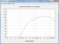
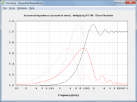
Yes it does.
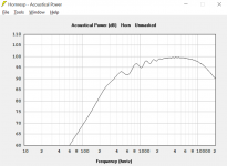
As can be seen from the Hornresp acoustical impedance chart, the acoustical impedance loading the driver diaphragm is dependent upon the solid angle into which the loudspeaker radiates. The legendary Klipschorn corner-horn system uses this principle to very good effect.
Kind regards,
David
Attachments
In a nutshell, the basic question is.... Does location in space (half, quarter, eighth, etc) actually effect the physical action/loading of the driver in the box?
If I take a box, that's performing perfectly (physically & electrically speaking - ignoring frequency response for the moment) while sitting in a corner of a room (0.5xPI), would that change (and if so, why) if I did nothing else but took that box out of the corner & hung it in the middle of space (4.0xPI)?
Yes, position matters, because the acoustic load changes. This is due to reflection, which effectively increases the pressure on the radiator (diaphragm, horn mouth etc).
You can view it this way: the acoustic load on, say, a diaphragm, is the ratio of pressure on the diaphragm to the velocity of the diaphragm. If you place the diaphragm near a wall, some of the pressure radiated from the diaphragm is reflected back by the wall, increasing the pressure on the diaphragm. That means the acoustic load increases. If you move the diaphragm away from the wall, the reflected pressure decreases, and so does the load.
There is some discussion of what happens when you place a horn close to a wall in Chapter 7 of my thesis:
Thesis
Does that happen in the real-world?
Yes, see the experimental verification in Chapter 9, in particular 9.4.
Hi Andreas,
<snip>
Hornresp assumes an axisymmetric horn, so there are no corners in which to position the simulated ports anyway
Translation: Hey Dix, if you'd happened to be paying enough attention to notice there's both electrical AND acoustical impedance plot results. A quick glace at the latter & you'd likely have been able to correctly speculate on the answer to your own d*mn question.As can be seen from the Hornresp acoustical impedance chart,...
(that "twack" you heard was me slapping myself in the back of my head)
A doctoral thesis to digest.... great, like I need another reason to drink more coffee & spend hours trying to learn stuff I'm too old to have any business knowing (much to the chagrin of my wife)There is some discussion of what happens when you place a horn close to a wall in Chapter 7 of my thesis: Thesis
Yes, see the experimental verification in Chapter 9, in particular 9.4.
All kidding aside, seriously, Dave & Bjorn, thanks to both of you. OK, so it actually does make sense & I get it. Pardon my ignorance, but when something doesn't quite make sense I tend to keep digging until I either figure out exactly what's wrong or what particular piece of the puzzle it is that I'm missing.
According to my wife it'll be one of those exact holes I dig that will be the one they bury me in.... but, that's a whole 'nuther sermon.
Thanks again.
- Home
- Loudspeakers
- Subwoofers
- Hornresp