It's at the bottom of David McBean's current posts:Hi all.
Please forgive me for asking a silly question, but where can I actually get the HornResp-programme?
Regards
Hornresp
But oddly, not in this thread's OP, which could be updated by him at any time.
David, if you do update the OP, for historical purposes it would be interesting to note when V.1 originated, and when the first web appearance occurred.
The thread is at 963,141 views, closing in on the million mark!
Art
Last edited:
It's at the bottom of David McBean's current posts:
Hornresp
But oddly, not in this thread's OP, which could be updated by him at any time.
David, if you do update the OP, for historical purposes it would be interesting to note when V.1 originated, and when the first web appearance occurred.
The thread is at 963,141 views, closing in on the million mark!
Art
Art you have the same amnesia that I have 😁
Hi Andre,
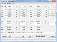
The format, contents and parameter order of the driver file should be as shown below:
RCF L18P400
Sd=1220.00
Bl=24.20
Cms=1.60E-04
Rms=4.51
Mmd=200.00
Le=2.50
Re=5.10
Pmax=1000
Xmax=9.0
LossyLe=0
Attempting to "hand craft" a driver file is definitely not recommended") .
.
Always let Hornresp generate your driver files using File > Copy Driver to Database, after first having entered the driver parameter values via the Input Parameters window.
Double-click on the Cms and Rms input boxes and follow the instructions to enter the equivalent Thiele-Small parameter values. If you would rather specify the driver using Thiele-Small parameters only (rather than a mix of Thiele-Small and electro-mechanical parameters) then double-click on the Sd input box.
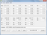
Using your given driver electro-mechanical values and calculating the required Cms and Rms values from Thiele-Small equivalents, your input parameters window should look like Attachment 1. Alternatively, using your given Thiele-Small values only, your input parameters window should look like Attachment 2.
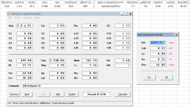
If the driver data is entered correctly, the initial values of the Semi-Inductance Model parameters (including Rss) will all be zero.
Kind regards,
David
Wanting to compute a simple vented box, here's my driver file (hand crafted):
RCF L18P400
Sd=1220.00
Bl=24.2
Mmd=200
Le=2.50
Re=5.10
Pmax=1000
Xmax=9.0
LossyLe=0
Qes=0.29
Qms=7.6
Qts=0.28
Vas=340
fs=29
Following your recommendation...
> Select the 'Rear Vented' option from the Chamber Type tool and set S1 to L45 = 0 and Vrc, Lrc, Ap and Lpt > 0.
However, after pasting the driver into the record I got "Invalid result. Change input data."
The format, contents and parameter order of the driver file should be as shown below:
RCF L18P400
Sd=1220.00
Bl=24.20
Cms=1.60E-04
Rms=4.51
Mmd=200.00
Le=2.50
Re=5.10
Pmax=1000
Xmax=9.0
LossyLe=0
Attempting to "hand craft" a driver file is definitely not recommended
.Always let Hornresp generate your driver files using File > Copy Driver to Database, after first having entered the driver parameter values via the Input Parameters window.
the RCF T/S params are missing Cms and Rms
Double-click on the Cms and Rms input boxes and follow the instructions to enter the equivalent Thiele-Small parameter values. If you would rather specify the driver using Thiele-Small parameters only (rather than a mix of Thiele-Small and electro-mechanical parameters) then double-click on the Sd input box.
Using your given driver electro-mechanical values and calculating the required Cms and Rms values from Thiele-Small equivalents, your input parameters window should look like Attachment 1. Alternatively, using your given Thiele-Small values only, your input parameters window should look like Attachment 2.
Double clicking on Le showed the following values in the Semi-Inductance Model window: RE', Leb, Le and Ke all filled in, but the Rss field empty.
If the driver data is entered correctly, the initial values of the Semi-Inductance Model parameters (including Rss) will all be zero.
Kind regards,
David
Attachments
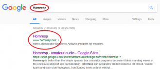
where can I actually get the HornResp-programme?
Hi neets,
Google is your friend
.Kind regards,
David
Attachments
But oddly, not in this thread's OP, which could be updated by him at any time.
Hi Art,
I did not realise that it was possible for me to edit my original post. Thanks for enlightening me
.Kind regards,
David
David,Hi Art,
I did not realise that it was possible for me to edit my original post. Thanks for enlightening me
Kind regards,
David
I was enlightened to that feature sometime between 2011 and 2014, have used it extensively as I continue to find more mistakes to redact in most of my OPs.
Editing one's other posts can be done by moderators by request if one fears that the errors are inhuman, and the divas won't forgive :^).
Art
David,
I was enlightened to that feature sometime between 2011 and 2014, have used it extensively as I continue to find more mistakes to redact in most of my OPs.
Editing one's other posts can be done by moderators by request if one fears that the errors are inhuman, and the divas won't forgive :^).
Art
There are divas on diyaudio!!!!
Say it ain't so.
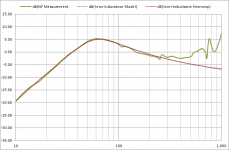
Many thanks for figuring out an elegant way to work these more advanced transducer models into Hornresp. As you can see in attachments #1 & #2, the semi-inductance model output from Hornresp provides a satisfying match with nearfield measurement for the Dayton Classic 12” subwoofer posted previously here: Inductance Cancellation Techniques…CHANGE 5
Semi-inductance and frequency-dependent damping (FDD) models have been added.
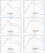
As another test, I decided to try and use the free-air impedance curve images posted on Databass to determine the semi-inductance parameters by hand. I chose two drivers that were on either end of the Lossy-Le correction spectrum, the Dayton HO18, and the ER Audio XXX 18. It would have been nice if a nearfield measurement was included in the Databass plot set, but I understand why it isn’t. So, to try and compare prediction to ground plane measurements an enclosure diffraction increment needs to be added(aka baffle step). I used the BTM diffraction method (Baffle edge diffraction with dipole radiation), although I think the EDGE diffraction tool would get you pretty close in this case.
For each woofer I calculated response with the Traditional TSP model, the Lossy-Le model, and the Semi-Inductance model. Each plot has 3 curves: blue= databass measurement, black dotted = 2pi calculated response, red = 2pi calculated response + diffraction. Pretty nice agreement considering the hand work involved in selecting the Semi-Inductance parameters and the estimate of diffraction. One thing I found interesting is that the HO18 inductance nearly provides built in baffle step compensation.
Attachments
Many thanks for figuring out an elegant way to work these more advanced transducer models into Hornresp. As you can see in attachments #1 & #2, the semi-inductance model output from Hornresp provides a satisfying match with nearfield measurement for the Dayton Classic 12” subwoofer posted previously here: Inductance Cancellation Techniques
As another test, I decided to try and use the free-air impedance curve images posted on Databass to determine the semi-inductance parameters by hand. I chose two drivers that were on either end of the Lossy-Le correction spectrum, the Dayton HO18, and the ER Audio XXX 18. It would have been nice if a nearfield measurement was included in the Databass plot set, but I understand why it isn’t. So, to try and compare prediction to ground plane measurements an enclosure diffraction increment needs to be added(aka baffle step). I used the BTM diffraction method (Baffle edge diffraction with dipole radiation), although I think the EDGE diffraction tool would get you pretty close in this case.
For each woofer I calculated response with the Traditional TSP model, the Lossy-Le model, and the Semi-Inductance model. Each plot has 3 curves: blue= databass measurement, black dotted = 2pi calculated response, red = 2pi calculated response + diffraction. Pretty nice agreement considering the hand work involved in selecting the Semi-Inductance parameters and the estimate of diffraction. One thing I found interesting is that the HO18 inductance nearly provides built in baffle step compensation.
Hi bolserst,
Excellent information - many thanks for posting it!
Kind regards,
David
THanks for the links and the data Steve.
And thanks to David who was willing to do the incorporation of all this advanced calculations into Hornresp.
Getting closer to the real deal is the sole aim of a good simulator.
I'm going to be doing a decently large sample sett of measurements in the next coming months. And I will be eagerly doing comparisons between these measurements and simulations via Hornresp.
The link in the thread pertaining to diffraction simulation is dead. Here is the current link:
http://gfx.cs.princeton.edu/gfx/pubs/_2009_AIE/calamia-phd-thesis.pdf
http://gfx.cs.princeton.edu/gfx/pubs/_2009_AIE/calamia-phd-thesis.pdf
There are divas on diyaudio!!!!
Say it ain't so.
Rotflmao!
Many thanks for figuring out an elegant way to work these more advanced transducer models into Hornresp. As you can see in attachments #1 & #2, the semi-inductance model output from Hornresp provides a satisfying match with nearfield measurement for the Dayton Classic 12” subwoofer posted previously here: Inductance Cancellation Techniques
As another test, I decided to try and use the free-air impedance curve images posted on Databass to determine the semi-inductance parameters by hand. I chose two drivers that were on either end of the Lossy-Le correction spectrum, the Dayton HO18, and the ER Audio XXX 18. It would have been nice if a nearfield measurement was included in the Databass plot set, but I understand why it isn’t. So, to try and compare prediction to ground plane measurements an enclosure diffraction increment needs to be added(aka baffle step). I used the BTM diffraction method (Baffle edge diffraction with dipole radiation), although I think the EDGE diffraction tool would get you pretty close in this case.
For each woofer I calculated response with the Traditional TSP model, the Lossy-Le model, and the Semi-Inductance model. Each plot has 3 curves: blue= databass measurement, black dotted = 2pi calculated response, red = 2pi calculated response + diffraction. Pretty nice agreement considering the hand work involved in selecting the Semi-Inductance parameters and the estimate of diffraction. One thing I found interesting is that the HO18 inductance nearly provides built in baffle step compensation.
Good work...I've been lurking along following this discussion but have not had much time for audio related endeavors lately. I do have close mic data for many sealed cab tests, but I don't include it in the graphs on DB. I'm not sure if I have it for the 2 example drivers exactly but I might. If you need it let me know and I'll see about emailing it to you.
REW can calculate parameters from imported impedance curves. Verified by exporting text files of measurements taken in LIMP.
Examples using RF T3S2-19 driver. Parameters calculated are slightly different but it should be close enough for modeling and to derive lossy inductance parameters to use.
If you can export text files of the impedance measurements you should be good to go by importing them into REW. I believe the S&L WT2/Pro and Dayton DATS can do this?
If you have the standard TS parameters and a text file with free-air impedance data (magnitude & phase) I have a spreadsheet that can determine the semi-inductance parameters. If you have text file for not only the free-air impedance, but the "added-mass" or "in-enclosure" impedance, you can just important them into REW for the parameter calculations.Is there any way to derive these enhanced parameters from standard Thiele/Small measurements?
Inductance Cancellation Techniques
ThanksGood work...I've been lurking along following this discussion but have not had much time for audio related endeavors lately. I do have close mic data for many sealed cab tests, but I don't include it in the graphs on DB. I'm not sure if I have it for the 2 example drivers exactly but I might. If you need it let me know and I'll see about emailing it to you.
I had sent an email a week or so ago to the Databass contact email address, not sure if that is the one to use. I will send PM with my email contact info. I think it would be interesting to compare at least one driver with near-field and ground plane measurements. It doesn't have to be either of the woofers previously posted. If you have data for any woofer that has noticeable inductance hump, that would be great. If you could send text or CSV data files of near field response, ground plane response, and free-air impedance that would make the comparison a lot easier, and avoid the visual overlays.
If you have the standard TS parameters and a text file with free-air impedance data (magnitude & phase) I have a spreadsheet that can determine the semi-inductance parameters. If you have text file for not only the free-air impedance, but the "added-mass" or "in-enclosure" impedance, you can just important them into REW for the parameter calculations.
Inductance Cancellation Techniques
I think you know my email address !
I would be most interested in getting a copy of that spreadsheet. My Smith&Larson WooferTester Pro does indeed give the text file with the free air impedance data.
Thanks
I had sent an email a week or so ago to the Databass contact email address, not sure if that is the one to use. I will send PM with my email contact info. I think it would be interesting to compare at least one driver with near-field and ground plane measurements. It doesn't have to be either of the woofers previously posted. If you have data for any woofer that has noticeable inductance hump, that would be great. If you could send text or CSV data files of near field response, ground plane response, and free-air impedance that would make the comparison a lot easier, and avoid the visual overlays.
I no longer check that email much. I will message you my personal email.
Hi all,
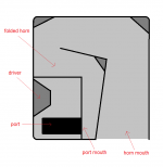
I just posted in the subwoofer forum with a question about whether it is possible to horn load a port.
See post here: http://www.diyaudio.com/forums/subwoofers/321975-subwoofer-horn-loaded-port.html#post5417612
I'm also interested in whether, if such a configuration is possible, it can be modelled in hornresp. Any ideas?
Many thanks.
A
Attachments
- Home
- Loudspeakers
- Subwoofers
- Hornresp