@ David McBean
Thanx for this
You were very quick
Thanx for this
Negative values can now be entered directly into the Rg text box, and the loudspeaker wizard Rg slider control has been modified to operate correctly with negative values. Also, negative values can now be copied and pasted into the Rg text box only.
You were very quick
I put in different values in HR until I got an electrical impedance plot that closely resembled the one in the data sheet.
.You were very quick
I didn't like being able to copy and paste negative values into places they shouldn't be
.Attachments
I didn't like being able to copy and paste negative values into places they shouldn't be
Negative flare is not an option! Awe man!!!!!
I guess if it was we might be able to find out if a horn could work as a vacuum?
Originally Posted by David McBean
I didn't like being able to copy and paste negative values into places they shouldn't be
Spoilsport
Unbelievable, the things that Hornresp users get up to.
Continuing with this glorious tradition, any tips on how to model a split horn - same driver, 2 or more horns?
Say, a single driver for 2 horns (or n, if you prefer). Sd gets halved; Vas gets halved. Anything else, given that the other half of the driver is loaded by an identical horn?
Any support for horn arrays?
Negative flare is not an option!
Hi Mark,
"Negative" negative flare is not an option, but "positive" negative flare still is, of course
.Just set S2 < S1.
Kind regards,
David
Attachments
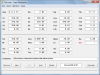
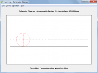
My dear friends, how to simulate the closed box with the driver offset, or closed transmission line with offset?
Hi mV8,
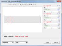
The arrangement shown below should get you reasonably close.
Use the Loudspeaker Wizard if you want to add absorbent filling material, and only consider the direct radiator output.
Kind regards,
David
Attachments
Hi SamAnytime,
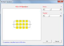
If you have two identical horns, simply specify a single horn with double the cross-sectional areas and chamber volumes of one of the horns, keeping axial lengths the same.
Use the Multiple Speakers tool to specify the desired array.
Kind regards,
David
any tips on how to model a split horn - same driver, 2 or more horns?
If you have two identical horns, simply specify a single horn with double the cross-sectional areas and chamber volumes of one of the horns, keeping axial lengths the same.
Any support for horn arrays?
Use the Multiple Speakers tool to specify the desired array.
Kind regards,
David
Attachments
Hi SamAnytime,
If you have two identical horns, simply specify a single horn with double the cross-sectional areas and chamber volumes of one of the horns, keeping axial lengths the same.
Use the Multiple Speakers tool to specify the desired array.
Kind regards,
David
Thanks, David. Now how to drive the array using a single driver?
Now how to drive the array using a single driver?
Hi SamAnytime,
The best that you can do with Hornresp is to the extend the technique used to model two identical horns connected to a single driver, to the number of horns in the array. In other words, specify a single large "composite" horn.
Kind regards,
David
Hi, Dear Mr. David McBean. Thank you, for the miracle program Hornresp
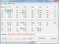
I would like to learn, how to accurately calculate the Tapped Horn in the car, this will be my third horn, and the first tapped horn.
1)
2)
I want to calculate the same:
Settings:
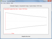
Scheme:
1 - I need this way
2 - Scheme hornresp
3 - So Horn scheme looks sketchup.
4 - Hornresp draws this
5 - I need this way
How to correctly calculate? Thanks in advance for your reply!
P.S My English is very bad
I would like to learn, how to accurately calculate the Tapped Horn in the car, this will be my third horn, and the first tapped horn.
1)
An externally hosted image should be here but it was not working when we last tested it.
An externally hosted image should be here but it was not working when we last tested it.
2)
An externally hosted image should be here but it was not working when we last tested it.
An externally hosted image should be here but it was not working when we last tested it.
I want to calculate the same:
An externally hosted image should be here but it was not working when we last tested it.
Settings:
An externally hosted image should be here but it was not working when we last tested it.
An externally hosted image should be here but it was not working when we last tested it.
Scheme:
An externally hosted image should be here but it was not working when we last tested it.
An externally hosted image should be here but it was not working when we last tested it.
1 - I need this way
2 - Scheme hornresp
3 - So Horn scheme looks sketchup.
4 - Hornresp draws this
5 - I need this way
How to correctly calculate? Thanks in advance for your reply!
P.S My English is very bad


I would like to learn, how to accurately calculate the Tapped Horn in the car, this will be my third horn, and the first tapped horn.
Hi Cubana,
The tapped horn model you are using looks fine to me. To gain a bit more flexibility in specifying the expansion profile near the horn mouth you could perhaps use four segments rather than three, with the second tap point at S4, but that is about the only change I would consider making.
Kind regards,
David
EDIT - The throat chamber seems a bit short when compared against your drawing. If Vtc = 20000 and Atc = 1000 then the length of the chamber is only 20 cm when the horn segment alongside is 228 cm. Did you mean Vtc to be 200000 perhaps?
Last edited:
The whole idea of using an array (for me at least) is to overcome the upper frequency limit while retaining the bass. Kind of hard to investigate that if you are going to treat the array as a single horn.Hi SamAnytime,
The best that you can do with Hornresp is to the extend the technique used to model two identical horns connected to a single driver, to the number of horns in the array. In other words, specify a single large "composite" horn.
Kind regards,
David
- Home
- Loudspeakers
- Subwoofers
- Hornresp