In the real world, when I use a first order high pass on a loudspeaker, there's a gentle 6dB per octave high pass.
In the absence of any further information on the specific example originally quoted, I have conducted a series of "sanity checks" using the Hornresp default record to hopefully confirm that the passive high pass filter model is indeed working correctly.
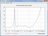
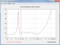
Attachments 1 and 2 show the default record electrical input impedance.
At 57.25 Hz the resistance is 55.811126 ohms and the reactance is 5.754179 ohms, giving a magnitude of 56.1070 ohms as indicated.
At 87.92 Hz the resistance is 8.301362 ohms and the reactance is -1.441046 ohms, giving a magnitude of 8.4255 ohms as indicated.
|Ze| = Sqrt(Re ^ 2 + Xe ^ 2)
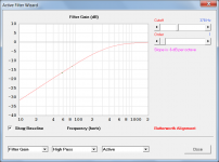
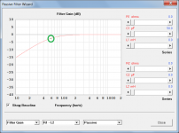
Attachment 3 shows the gain of a first-order high pass filter with C = 50 microfarads and the filter loaded by the default record electrical input impedance. Filter gain values at 57.25 Hz and 87.92 Hz are shown as green dots inside the green circles.
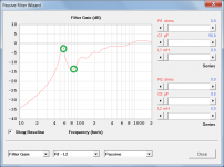
Attachment 4 shows the gain of a first-order high pass filter with C = 50 microfarads and the filter loaded by a constant 55.811126 ohms resistance plus 5.754179 ohms reactance. As expected, the gain value at 57.25 Hz is identical to that shown in Attachment 3.
The Attachment 4 rolloff corner frequency is given by fc = 1 / (2 * Pi * |Ze| * C)
fc = 1 / (2 * Pi * 56.1070 * 50 * 10 ^ -6) = 57 Hz (rounded)
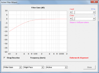
Attachment 5 shows the gain of a first-order high pass filter with C = 50 microfarads and the filter loaded by a constant 8.301362 ohms resistance minus 1.441046 ohms reactance. As expected the gain value at 87.92 Hz is identical to that shown in Attachment 3.
The Attachment 5 rolloff corner frequency is given by fc = 1 / (2 * Pi * |Ze| * C)
fc = 1 / (2 * Pi * 8.4255 * 50 * 10 ^ -6) = 378 Hz (rounded)
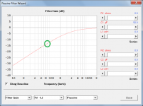
Attachment 6 shows the gain of an active first-order 57 Hz high pass filter. The curve is identical to the gain of the passive filter shown in Attachment 4 when allowances are made for the slight discrepancies due to rounding of values used in the example. The passive and active filter phase and delay charts are also identical.
Attachment 7 shows the gain of an active first-order 378 Hz high pass filter. The curve is identical to the gain of the passive filter shown in Attachment 5 when allowances are made for the slight discrepancies due to rounding of values used in the example. The passive and active filter phase and delay charts are also identical.
In Hornresp, there's a big peak at the driver's impedance. A peak that I don't see in the real world.
The only thing I can think of that might explain the difference seen is that in the real world, the electrical input impedance peak could possibly be less than that predicted due to cabinet losses not taken into account by Hornresp. This would then also accordingly reduce the peak in the measured filter gain.
Does anyone else have a different (i.e. better) explanation, perhaps?
I understand, that "technically" the filter should do virtually nothing at the driver's resonance, because the impedance at the driver's resonance is so high.
The results of the above tests, in particular those shown in Attachments 4 and 5, would tend to suggest otherwise
") .
.Attachments
Happy New Year David,
Thanks - and a very Happy New Year to you and yours, Bill.
Kind regards,
David
Hi,
Uli
I remind you, that Hornresp is wrong in any and all "acoustical power" plots, which it plots. It plots a certain pressure, not power.
Uli
Nobody cared the last time you said it and nobody cares now. The graph shows us what we want to see and we are not concerned with the graph title. If you like you can cross out the word "power" and write in "pressure" when you print out your Hornresp graphs.
As I understand it, the graph shows "power response" and uses the word "power" to differentiate from "axial response" or directly on axis response like what MJK shows in his graphs..
As I understand it, the graph shows "power response" and uses the word "power" to differentiate from "axial response" or directly on axis response like what MJK shows in his graphs..
Hi,
I remind you, that Hornresp is wrong in any and all "acoustical power" plots, which it plots. It plots a certain pressure, not power.
Uli
No analysis is going to be perfect, you have to look for the relation between analysis and finished to get a feel as to what you can expect.
Sent from my iPhone using Tapatalk
Simulate a driver at first in a minimum closed baffle and at second in an infinite baffle and compare. At lo frequencies, where the piston is not big enuff yet to beam, Hornresp colports a 6dB rise, whereas in the real world sonic power rises only by 3dB. Pressure rises by 6dB. Such are the basics.
There is. To thee, power is a state, average of pressure. To me, power is a flow, energy per time. If one infinitesimally extends a minimum closed baffle, energy per time radiated is doubled, not quadrupled.
Back to your arguments that have been discussed and answers given. Nobody is making you use this "flawed" program Uli.
If you don't like it, or find it accurate, or useful, don't use the program.
It upsets me that a person could hold the work of Mr. McBean of so little value that he nit picks it to death. This program is older than most of the people using it. And has gone through many serious improvements. I can think of quite a few people that support it in the back ground finding papers or writing code to aid in the development of Hornresp.
If there is a legitimate problem it gets fixed and pretty quickly at that.
So make your case to anyone that sees a bug or an inaccuracy. And then wait for a response from the man who makes it all work.
David has been very patient with many careful well thought out answers over quite a few years.
The man deserves respect.
So treat him respectfully Uli!
mark i should have left my post up.
deleted it cause i thought it was a little harsh.
I really hate it when anybody is disrespectful of a person who has earned the respect of so many.
I'm not deleting what I wrote.
I'm just trying to get to grips with hornresp. I hope to make a variation of the TABAQ loaded transmission line cabinets. I have attached the TABAQ section and the hornresp input parameters, could someone please check these out and see if if the paramater data is correct. Cheers.
Attachments
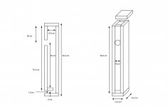
Some dimensions are missing.
S1 is the beginning of the path length. Is the 128 cm^2 the area of the hole that the driver sits in?
Thanks for looking at this. The 128cm2 is the internal top face of the cabinet (10x12.8cm). The driver cutout is 7.57cm dia/45cm2.
Hornresp Update 4030-170109
Hi Everyone,
BUG FIXES
Further to my Post #6941, two bugs were found while conducting additional tests and code checks to conclusively confirm that the passive filter model in the Filter Wizard tool was working correctly.
BUG 1
If Rg was not zero and a new baseline was set by pressing the Crtl+Alt+B keys, the new baseline for the Filter Gain chart was incorrectly generated. This bug has now been fixed. It applied to both the Passive and Le Cléac'h filter options.
BUG 2
If a passive filter was specified with components connected in parallel rather than series, the parallel settings were not permanently saved when the Save button was clicked or the F9 function key was pressed. This bug has now been fixed.
The two bugs had no effect on the passive filter results queried by 'Patrick Bateman' in Post #6924. It seems from all the testing that I have now done that the Filter Wizard tool is working correctly.
Kind regards,
David
I'm just trying to get to grips with hornresp. I hope to make a variation of the TABAQ loaded transmission line cabinets. I have attached the TABAQ section and the hornresp input parameters, could someone please check these out and see if if the paramater data is correct. Cheers.
Hi CUTTING EDGE CNC,
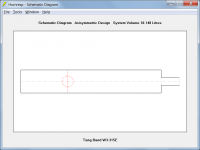
A possible alternative model could be as shown in the attachments.
Kind regards,
David
EDIT - Use the Loudspeaker Wizard to add the necessary absorbent filling material to the transmission line.
Attachments
Last edited:
- Home
- Loudspeakers
- Subwoofers
- Hornresp