David,
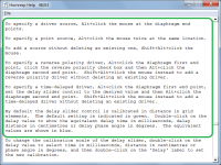
On my screen the driver source is not visible. The waves are visible though I have to set it to 1 iteration/frame for it to simulate the waves the way the previous version did.
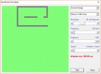
Admittedly the last time I used the wave simulator heavily was prior to upgrading to windows 10. Attached picture shows a crude outline with a driver source, though the white line that is usually there (driver source) is not visible on my screen.
Thank you kindly.
On my screen the driver source is not visible. The waves are visible though I have to set it to 1 iteration/frame for it to simulate the waves the way the previous version did.
Admittedly the last time I used the wave simulator heavily was prior to upgrading to windows 10. Attached picture shows a crude outline with a driver source, though the white line that is usually there (driver source) is not visible on my screen.
Thank you kindly.
Attachments
David,
On my screen the driver source is not visible. The waves are visible though I have to set it to 1 iteration/frame for it to simulate the waves the way the previous version did.
Admittedly the last time I used the wave simulator heavily was prior to upgrading to windows 10. Attached picture shows a crude outline with a driver source, though the white line that is usually there (driver source) is not visible on my screen.
Thank you kindly.
Hi six7one,
This is very interesting. Unless it is a problem specific to your display monitor, it would seem that the Hornresp Wavefront Simulator works okay for Microsoft Windows Operating Systems up to and including Windows 7, but not for Windows 10. I wonder if any other Windows 10 users have experienced the same problem as you?
(Feedback from other Windows 10 users would be greatly appreciated at this stage).
Kind regards,
David
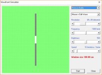
EDIT - Just an afterthought - six7one, could you please post a screenprint of the 'Piston in Baffle' option.
Last edited:
EDIT - Just an afterthought - six7one, could you please post a screenprint of the 'Piston in Baffle' option.
This is strange.
Piston in baffle shows the driver source in white.
When I do a custom driver source the white line is not visible.
Attachments
Hello David.
Me again!")
I'm on a new iteration of my midrange horn and wondering what's the right way of modelling it.
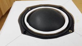
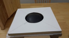
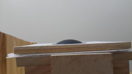
Assuming an axisymmetrical horn, I modelled with S1=Sd=94.2cm2. But then it seemed a good idea to reduce Vtc so I adopted a 4" dustcap to be glued to the cone. See the attached.
The white ring is to be glued to the bottom of the white plate (throat), reducing the chamber volume. The white plate has circular cut at 45° where the smaller side of the hole is 90mm diameter.
Given this configuration, what should I use for S1, Vtc, and Atc to properly model in Hornresp?
Thank you!
Me again!
I'm on a new iteration of my midrange horn and wondering what's the right way of modelling it.
Assuming an axisymmetrical horn, I modelled with S1=Sd=94.2cm2. But then it seemed a good idea to reduce Vtc so I adopted a 4" dustcap to be glued to the cone. See the attached.
The white ring is to be glued to the bottom of the white plate (throat), reducing the chamber volume. The white plate has circular cut at 45° where the smaller side of the hole is 90mm diameter.
Given this configuration, what should I use for S1, Vtc, and Atc to properly model in Hornresp?
Thank you!
Attachments
Hi six7one and Sabbelbacke,
Just checking - with a custom design the source / driver needs to be specified by the user. Have you done this?
Kind regards,
David
This is strange.
Piston in baffle shows the driver source in white.
When I do a custom driver source the white line is not visible.
Using WIn10 64 Bit, in "custom design" I see no source, either.
Just checking - with a custom design the source / driver needs to be specified by the user. Have you done this?
Kind regards,
David
Attachments
Last edited:
Hello David.
Me again!
I'm on a new iteration of my midrange horn and wondering what's the right way of modelling it.
Assuming an axisymmetrical horn, I modelled with S1=Sd=94.2cm2. But then it seemed a good idea to reduce Vtc so I adopted a 4" dustcap to be glued to the cone. See the attached.
The white ring is to be glued to the bottom of the white plate (throat), reducing the chamber volume. The white plate has circular cut at 45° where the smaller side of the hole is 90mm diameter.
Given this configuration, what should I use for S1, Vtc, and Atc to properly model in Hornresp?
Thank you!
Hi LewinskiH01,
Not sure about the S1, Vtc and Atc values.
Don't use the 4" dustcap.
The horn throat area appears to be larger than the driver diaphragm area. This is not good practice in a midrange horn as it results in a significant discontinuity at the throat.
Kind regards,
David
Hi six7one and Sabbelbacke,
With a custom design the source / driver needs to be specified by the user. Have you done this?
Kind regards,
David
Huh, how about that.
In previous versions I would select the "Mouse = Edit Wave" option and simply click the points to make the driver source area which would show the source area in a white line.
In this version selecting the "Mouse = Edit Wave" option still produces a driver source area though no white line is generated.
I could also be recalling the steps differently from the last time I used the wave tool.
Either way I am able to produce the white line for the driver source area now. Lesson learned...always refer to the help file
Thank you kindly.
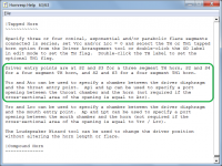
That was an easy one - problem solved
.The way that sources / drivers are specified had to be changed to allow the multiple, reverse polarity and time-delayed source options to be added.
https://www.youtube.com/watch?v=TYfRyt6OQkY
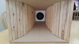
Nice way to make a smooth sided horn with MDF.
The trick is to cut just deep enough to allow the bend you require.
You can do the cuts with a table saw, or even a hand held circular saw.
And if you are limited to a hand saw. It is still possible to create this type of cut.
Nice way to make a smooth sided horn with MDF.
The trick is to cut just deep enough to allow the bend you require.
You can do the cuts with a table saw, or even a hand held circular saw.
And if you are limited to a hand saw. It is still possible to create this type of cut.
Hello David,
Its obvious to me that you strive to maintain Hornresp in an impeccable manner, so hopefully this post will prove to be helpful and not a wild goose chase!
I have noticed a possible minor bug in Hornresp. I say "possible minor bug" because my platform is a non-standard one, currently using WinXP 32 bit running as a virtual machine on Linux, so this minor issue may not be real in a standard environment. I have only been working with OD horns lately too, so haven't tested this issue fully.
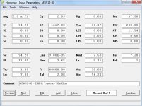
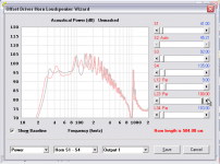
The issue I've noticed in Hornresp has to do with the "L23 Par" slider inside the Loudspeaker Horn Wizard. When attempting to drag (or click) the L23 Par slider beyond 100 cm using the mouse, the slider stops at 100 like all the other sliders do, but does not reset the scale (as the other sliders do), so that I can continue beyond 100 cm. At this point is a hard stop and clicking the arrow or attempting to drag the slider further beyond 100 is not possible until clicking the "Save" button, then restarting the wizard. After restarting the wizard the L23 Par slider works fine from 100 to 200, then fails to reset the scale again. It seems to happen at every 100 cm slider interval.
I don't mind this slider behavior at all (generally only encountering it once in most horn designs), but since the other sliders in the wizard reset the scales for the user to continue, I assume you want to know if the L23 Par slider behavior differs from your intention. A screen shot example is below showing the mouse on the offending slider arrow. If I can help you any at all, please let me know.

Thank you!!!!
Its obvious to me that you strive to maintain Hornresp in an impeccable manner, so hopefully this post will prove to be helpful and not a wild goose chase!
I have noticed a possible minor bug in Hornresp. I say "possible minor bug" because my platform is a non-standard one, currently using WinXP 32 bit running as a virtual machine on Linux, so this minor issue may not be real in a standard environment. I have only been working with OD horns lately too, so haven't tested this issue fully.
The issue I've noticed in Hornresp has to do with the "L23 Par" slider inside the Loudspeaker Horn Wizard. When attempting to drag (or click) the L23 Par slider beyond 100 cm using the mouse, the slider stops at 100 like all the other sliders do, but does not reset the scale (as the other sliders do), so that I can continue beyond 100 cm. At this point is a hard stop and clicking the arrow or attempting to drag the slider further beyond 100 is not possible until clicking the "Save" button, then restarting the wizard. After restarting the wizard the L23 Par slider works fine from 100 to 200, then fails to reset the scale again. It seems to happen at every 100 cm slider interval.
I don't mind this slider behavior at all (generally only encountering it once in most horn designs), but since the other sliders in the wizard reset the scales for the user to continue, I assume you want to know if the L23 Par slider behavior differs from your intention. A screen shot example is below showing the mouse on the offending slider arrow. If I can help you any at all, please let me know.
Thank you!!!!
Attachments
David,
I have come into another scenario that I hope you could clarify.
As I have said before I have been using the BP6 selection to model series tuned BP6.
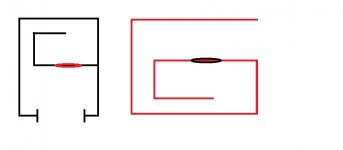
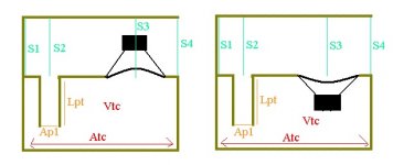
The layouts I have been using are "traditional" layouts for series tuned BP6 (black box in attached picture).
I wanted to play with a tapped concept series tuned BP6 (red box in attached picture).
To play with the tapped concept I modeled the BP6 (per a tutorial I found on another forum/thread) using the TH arrangement and specifying the appropriate values in their proper places.
Given the same airspace for the front and rear chambers and the same port areas and lengths but both modeled differently (via BP6 and the other via TH) the response curve, displacement, and spl are different.
I wasn't sure if (but I believe) having the driver cone fire into the path of the port will affect response and possibly displacement.
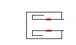
The ultimate goal is to model the layout in the second attachment. I understand how to model a simple tapped transmission line (thanks to tutorials) though that is a bit easier as it is a single line and hornresp models this perfectly.
I have seen the layout I want to model (second attachment) listed as a quasi 6th order though the three con sections have me a bit confused at this point. For reference:Hornresp for Dum... hmm... Everyone - Page 2 - Home Theater Forum and Systems - HomeTheaterShack.com
Really my question after all this is, would using the BP6 arrangement/wizard be able to accurately model a quasi-6th layout like the one in the second attachment (two drivers opposite each other) or would I have to fall back to the TH method? If falling back to the TH method, where do the CON values derive from?
Thank you kindly.
I have come into another scenario that I hope you could clarify.
As I have said before I have been using the BP6 selection to model series tuned BP6.
The layouts I have been using are "traditional" layouts for series tuned BP6 (black box in attached picture).
I wanted to play with a tapped concept series tuned BP6 (red box in attached picture).
To play with the tapped concept I modeled the BP6 (per a tutorial I found on another forum/thread) using the TH arrangement and specifying the appropriate values in their proper places.
Given the same airspace for the front and rear chambers and the same port areas and lengths but both modeled differently (via BP6 and the other via TH) the response curve, displacement, and spl are different.
I wasn't sure if (but I believe) having the driver cone fire into the path of the port will affect response and possibly displacement.
The ultimate goal is to model the layout in the second attachment. I understand how to model a simple tapped transmission line (thanks to tutorials) though that is a bit easier as it is a single line and hornresp models this perfectly.
I have seen the layout I want to model (second attachment) listed as a quasi 6th order though the three con sections have me a bit confused at this point. For reference:Hornresp for Dum... hmm... Everyone
- Page 2 - Home Theater Forum and Systems - HomeTheaterShack.comReally my question after all this is, would using the BP6 arrangement/wizard be able to accurately model a quasi-6th layout like the one in the second attachment (two drivers opposite each other) or would I have to fall back to the TH method? If falling back to the TH method, where do the CON values derive from?
Thank you kindly.
Attachments
I have noticed a possible minor bug in Hornresp. I say "possible minor bug" because my platform is a non-standard one, currently using WinXP 32 bit running as a virtual machine on Linux, so this minor issue may not be real in a standard environment.
Hi specd,
Many thanks for the feedback, it is greatly appreciated!
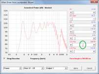
Unfortunately in this case it seems that the problem may be due to the non-standard platform you are using, as you suggested. For me, using the same length values as you, the L23 slider position is set halfway, not at the right-hand end, and works correctly (see attachment).
Kind regards,
David
Attachments
The ultimate goal is to model the layout in the second attachment.
Hi six7one,
Using the "principle of mirror images", the layout you want to model is just two of the red cabinets side by side (visualise a line down the centre of the layout you want to model, dividing it into two identical halves).
Either model a single red cabinet radiating into half the space you actually intend using, or use the Multiple Speakers tool to model two red cabinets connected in parallel radiating into the actual space you intend using. The results should be the same.
Kind regards,
David
When attempting to drag (or click) the L23 Par slider beyond 100 cm using the mouse, the slider stops at 100 like all the other sliders do, but does not reset the scale (as the other sliders do), so that I can continue beyond 100 cm.
What happens if you type in the desired length after clicking the slider?
Hi six7one,
Using the "principle of mirror images", the layout you want to model is just two of the red cabinets side by side (visualise a line down the centre of the layout you want to model, dividing it into two identical halves).
Either model a single red cabinet radiating into half the space you actually intend using, or use the Multiple Speakers tool to model two red cabinets connected in parallel radiating into the actual space you intend using. The results should be the same.
Kind regards,
David
David,
Thanks for that recommendation. While that makes sense and is a good way of modeling it, the area I am really confused on is the con/L12/L23/L34 areas.
In a horn or even tapped transmission line, the con/L values are the distances of s1 to s2 center, s2 center to s3 center, and s3 to s4. This is easy to deduce as most horns and transmission lines are essentially long line enclosures and finding the distances is easier.
In a series tuned 6th order with a slot or round port, are the con values derived by tracing the path through the port?
In the reference thread I linked to in my earlier post, the diagram shows a layout of the sample enclosure (attached) but makes no mention of how the thread author derived the con/L values for that particular layout.
Thank you kindly.
Attachments
Unfortunately in this case it seems that the problem may be due to the non-standard platform you are using, as you suggested. For me, using the same length values as you, the L23 slider position is set halfway, not at the right-hand end, and works correctly (see attachment).
Kind regards,
David
Very well! Thank you David.
In the reference thread I linked to in my earlier post, the diagram shows a layout of the sample enclosure (attached) but makes no mention of how the thread author derived the con/L values for that particular layout.
Hi six7one,
The system shown in your attachment is simply a standard three segment TH horn, but with a relatively large chamber and port inserted between the driver diaphragm and the throat entry point. The length values are specified the same as for any other tapped horn system, with L12 being the segment 1 axial length between S1 and S2, L23 being the segment 2 axial length between S2 and S3, and L34 being the segment 3 axial length between S3 and S4.
Note that the port length Lpt shown in your attachment is now specified as Lp in Hornresp.
Kind regards,
David
Attachments
- Home
- Loudspeakers
- Subwoofers
- Hornresp