Hi LewinskiH01,
Correct. Nd = 2P.
Correct.
S1 is correct, L12 is close enough (the actual L12 axial length down the centre-line of each of the tapered segment 1 ducts will be a little longer than 24 inches).
Correct.
Correct.
Vrc is the total volume of the combined chamber, as shared by the two drivers (38" x 19" x 6" or 2.5 cubic feet).
At lower frequencies the 1 * Pi model is probably more appropriate, at higher frequencies the 2 * Pi model is probably better. Suggest you try both and see how much the results differ, bearing in mind that the actual performance will probably lie somewhere between the two sets of predictions.
Kind regards,
David
There are two drivers, so Nd=2, and they are "normal" parallel.
Correct. Nd = 2P.
Second section has S3=36x36", S2=24x24", and L23=24"
Correct.
How about the first section? S1=2x5.75"x12"? and L12=24"
S1 is correct, L12 is close enough (the actual L12 axial length down the centre-line of each of the tapered segment 1 ducts will be a little longer than 24 inches).
So what about the drivers? Sd would be that of a single driver, like the T/S parameters.
Correct.
Vtc and Atc would be that of the two drivers added?
Correct.
And the rear chamber volume would be of the combined chamber, or half that?
Vrc is the total volume of the combined chamber, as shared by the two drivers (38" x 19" x 6" or 2.5 cubic feet).
And for a horn playing from 80 to 400Hz and having its mouth sitting on the floor and 1.5m away from the front wall should I use 2*pi or 1*pi?
At lower frequencies the 1 * Pi model is probably more appropriate, at higher frequencies the 2 * Pi model is probably better. Suggest you try both and see how much the results differ, bearing in mind that the actual performance will probably lie somewhere between the two sets of predictions.
Kind regards,
David
David
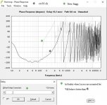
I made the ratio lower, but still have "warning s1<sd", but it fixed my dip in low corner. I have this weird phase shift thing happening, is this something that's going to be a problem?
thanks
Mike

Hi Mike,
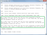
See the enclosed Pictures for answers.
b
")
Attachments
Hi LewinskiH01,
Correct. Nd = 2P.
Correct.
S1 is correct, L12 is close enough (the actual L12 axial length down the centre-line of each of the tapered segment 1 ducts will be a little longer than 24 inches).
Correct.
Correct.
Vrc is the total volume of the combined chamber, as shared by the two drivers (38" x 19" x 6" or 2.5 cubic feet).
At lower frequencies the 1 * Pi model is probably more appropriate, at higher frequencies the 2 * Pi model is probably better. Suggest you try both and see how much the results differ, bearing in mind that the actual performance will probably lie somewhere between the two sets of predictions.
Kind regards,
David
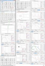
I meant to add that if you are not sure what cross-sectional areas and/or chamber sizes to use with multiple drivers, simply check the schematic diagram - it shows the system being simulated, drawn to scale. Move the mousepointer over a chamber to confirm the volume being used in the simulation. Multiple drivers are represented by a single composite driver, with the diaphragm diameter increased accordingly.
Hornresp Update 3970-160512
Hi Everyone,
BUG FIX
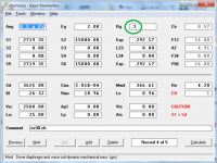
I noticed a bug in the Input Parameters window screenprints attached to Posts #6291 and #6292. The screenprint associated with the second-mentioned post is copied below.
Under some conditions it was possible to key a value into one input box then move to another box without the value in the first box being automatically converted to the correct format (.3 in the attachment should have automatically changed to 0.30 and been right-justified, when the Rg input box lost the focus).
This bug has now been fixed.
My thanks to Mike ('Angelow') for inadvertently bringing this problem to my attention.
Kind regards,
David
Hi Everyone,
BUG FIX
I noticed a bug in the Input Parameters window screenprints attached to Posts #6291 and #6292. The screenprint associated with the second-mentioned post is copied below.
Under some conditions it was possible to key a value into one input box then move to another box without the value in the first box being automatically converted to the correct format (.3 in the attachment should have automatically changed to 0.30 and been right-justified, when the Rg input box lost the focus).
This bug has now been fixed.
My thanks to Mike ('Angelow') for inadvertently bringing this problem to my attention
.Kind regards,
David
Attachments
Last edited:
Sharp shooter as usual!
Hi Mark,
Just call me "eagle eyes"
.Kind regards,
David
Attachments

Hello David,
I have learned to use hornresp through a combination of tutorials and the help file.
I noticed something that has me a bit confused as it seems to affect the response graphs (power, displacement, etc.).
When entering the T/S parameters for a driver the Re value (given by the manufacturer) can be a series or parallel result (for dual voice coils).
When choosing the number of drivers (Nd = 1 driver with Re) the response curve is calculated according to this value, I believe.
When entering Eg (amplifier power) the dialogue requests power in watts and load impedance in ohms.
Wouldn't it be easier to ask for power in watts and set load impedance based on driver arrangement?
On the case of dual voice coils, while Re may given by the manufacturer as the point at which the T/S parameters are derived, there are instances where the voice coils may be wired opposite by the user.
Example = Driver with Re 1.73 (per manufacturer) where driver is a dual 4 ohm voice coil. It cannot be specified (in driver arrangement) that the single driver will be wired to a single 8 ohm impedance.
How does Eg (amplifier power) affect the response when Eg is listed as 400 watts @ 8 ohms when Nd = 1 driver at 1.73?
Example = 4 dvc 4 ohm drivers; each driver with Re 1.73; Two amplifiers will be driving two subs each; each amplifier will see at least a 1 ohm load; all 4 will be wired 4P (dual 4 ohm voice coil); amplifier wattage can then be listed as "power in watts" at 1 ohm (2 drivers presenting 1 ohm to each amplifier; 4 drivers 1 ohm total); hornresp lists 4P = 0.43; In essence 4 drivers wired in parallel but due to the use of two amplifiers the final load impedance will actually be at least 1 ohm across 4 drivers.
I might have gotten confusing there but basically there is no way to set driver arrangement per "real world" wiring schematic/scenario such as 4 dvc drivers, wired in parallel at the driver, and then split between two amplifiers, which would result in (given Re = 1.73) 4 drivers being driven at 1 ohm (2 drivers in parallel = 1 ohm; 2 sets of 1 ohm pairs).
When setting these particular drivers to 4P = 0.43 the driver displacement is well above the physical ability of the driver.
When setting these particular drivers to 2P2S = 1.73 the driver displacement is well below the physical ability of the driver.
Eg (amplifier power) is entered as being at a 1 ohm load.
Am I confusing any of this? I have built an enclosure I have modeled based on hornresp but 2P2S suggests excursion is under control while 4P (real world wiring) suggests excursion is beyond the drivers physical ability.
Hi six7one,
Eg is the amplifier open-circuit voltage, not the amplifier output power. When Rg = 0 the amplifier output voltage is constant and equal to Eg. The only exception to this is when the Maximum SPL tool is used and constant power rather than constant voltage is applied to the speaker system - unless displacement-limited. Hornresp assumes a single amplifier, even when a multiple speaker array is specified.
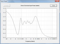
When the Calculate Parameter tool is used with Eg, the default power is set at 1 watt and the default load impedance is set at 8 ohms so that the default calculated value of Eg equates to the generally-accepted standard input voltage of 2.83 volts (representing 1 watt into a nominal 8 ohm resistive load). It is up to the user to decide what value of power and nominal load impedance to assume, bearing in mind that the power will only apply at the specified nominal impedance. The actual power supplied to the loudspeaker system will vary considerably from the nominal value because a constant voltage is being applied to a frequency-dependent changing impedance. The attachment shows the input power applied to the default record, when Eg is a constant 2.83 volts.
Hornresp assumes that all drivers have single voice coils.
400 watts into an 8 ohm resistive load requires an input voltage of 56.57 volts, which is the value of Eg calculated and used by Hornresp. Remember that the value of Eg remains constant regardless of the actual input impedance of the loudspeaker system, which as mentioned earlier and can be seen from the Hornresp electrical impedance chart, varies greatly with frequency. The nominal 1.73 ohm value only applies with a direct current signal.
In summary - Hornresp assumes a single amplifier with a constant open-circuit voltage of Eg, and drivers with single voice coils.
Kind regards,
David
When entering Eg (amplifier power) the dialogue requests power in watts and load impedance in ohms.
Eg is the amplifier open-circuit voltage, not the amplifier output power. When Rg = 0 the amplifier output voltage is constant and equal to Eg. The only exception to this is when the Maximum SPL tool is used and constant power rather than constant voltage is applied to the speaker system - unless displacement-limited. Hornresp assumes a single amplifier, even when a multiple speaker array is specified.
Wouldn't it be easier to ask for power in watts and set load impedance based on driver arrangement?
When the Calculate Parameter tool is used with Eg, the default power is set at 1 watt and the default load impedance is set at 8 ohms so that the default calculated value of Eg equates to the generally-accepted standard input voltage of 2.83 volts (representing 1 watt into a nominal 8 ohm resistive load). It is up to the user to decide what value of power and nominal load impedance to assume, bearing in mind that the power will only apply at the specified nominal impedance. The actual power supplied to the loudspeaker system will vary considerably from the nominal value because a constant voltage is being applied to a frequency-dependent changing impedance. The attachment shows the input power applied to the default record, when Eg is a constant 2.83 volts.
On the case of dual voice coils, while Re may given by the manufacturer as the point at which the T/S parameters are derived, there are instances where the voice coils may be wired opposite by the user.
Hornresp assumes that all drivers have single voice coils.
How does Eg (amplifier power) affect the response when Eg is listed as 400 watts @ 8 ohms when Nd = 1 driver at 1.73?
400 watts into an 8 ohm resistive load requires an input voltage of 56.57 volts, which is the value of Eg calculated and used by Hornresp. Remember that the value of Eg remains constant regardless of the actual input impedance of the loudspeaker system, which as mentioned earlier and can be seen from the Hornresp electrical impedance chart, varies greatly with frequency. The nominal 1.73 ohm value only applies with a direct current signal.
In summary - Hornresp assumes a single amplifier with a constant open-circuit voltage of Eg, and drivers with single voice coils.
Kind regards,
David
Attachments
Hornresp assumes that all drivers have single voice coils.
In summary - Hornresp assumes a single amplifier with a constant open-circuit voltage of Eg, and drivers with single voice coils.
Kind regards,
David
So if I understand this correctly, regardless of the ohm load stated in the driver arrangement config (Nd = 1 driver 1.73 ohms) the power and resistance I enter into Eg is what is used to predict the response curve?
Since hornresp assumes single voice coils, and I want to model 4 dvc drivers, should I set them as all parallel, all series or 2P2S?
Simply put, what would be the "correct" way, according to hornresp, to model 4 dvc drivers in a given enclosure space and find out what it's response curve would be given a specific amount of amplifier power at a nominal impedance?
Many thanks for this program by the way. I have this as my top preference compared to WinISD.
Hi six7one,
The response curve is predicted using the amplifier open-circuit voltage value shown in the Eg input box, unless the Maximum SPL tool is used.
How the four drivers are connected is up to you, depending upon the amplifier load required.
If we assume that the manufacturer's specifications for the dual voice-coil driver are:
Re = 6 ohms
Le = 2 mH
Bl = 15 T.m
Then to model the dual voice-coil driver with the coils connect in parallel, the following values should be entered into Hornresp:
Re = 3 ohms
Le = 1 mH
Bl = 15 T.m
To model the dual voice-coil driver with the coils connect in series, the following values should be entered into Hornresp:
Re = 12 ohms
Le = 4 mH
Bl = 30 T.m
The connection together of the four drive units is then specified using the Driver Arrangement tool. The three possible configurations are 4P, 4S or 2P2S.
As explained previously, modern solid-state amplifiers are constant voltage sources, not constant power sources. Amplifier power will vary considerably with frequency as the electrical impedance of the loudspeaker system changes. If you wish, the Maximum SPL tool can be used to generate the response curve for a constant input power rather than a constant input voltage. Set the maximum displacement value to 99.9 so that the response is not displacement limited.
Kind regards,
David
So if I understand this correctly, regardless of the ohm load stated in the driver arrangement config (Nd = 1 driver 1.73 ohms) the power and resistance I enter into Eg is what is used to predict the response curve?
The response curve is predicted using the amplifier open-circuit voltage value shown in the Eg input box, unless the Maximum SPL tool is used.
Since hornresp assumes single voice coils, and I want to model 4 dvc drivers, should I set them as all parallel, all series or 2P2S?
How the four drivers are connected is up to you, depending upon the amplifier load required.
Simply put, what would be the "correct" way, according to hornresp, to model 4 dvc drivers in a given enclosure space
If we assume that the manufacturer's specifications for the dual voice-coil driver are:
Re = 6 ohms
Le = 2 mH
Bl = 15 T.m
Then to model the dual voice-coil driver with the coils connect in parallel, the following values should be entered into Hornresp:
Re = 3 ohms
Le = 1 mH
Bl = 15 T.m
To model the dual voice-coil driver with the coils connect in series, the following values should be entered into Hornresp:
Re = 12 ohms
Le = 4 mH
Bl = 30 T.m
The connection together of the four drive units is then specified using the Driver Arrangement tool. The three possible configurations are 4P, 4S or 2P2S.
and find out what it's response curve would be given a specific amount of amplifier power at a nominal impedance?
As explained previously, modern solid-state amplifiers are constant voltage sources, not constant power sources. Amplifier power will vary considerably with frequency as the electrical impedance of the loudspeaker system changes. If you wish, the Maximum SPL tool can be used to generate the response curve for a constant input power rather than a constant input voltage. Set the maximum displacement value to 99.9 so that the response is not displacement limited.
Kind regards,
David
Last edited:
David,
Thanks for your responses so far. I have looked at the maximum spl tool and also, fault on my part, realized that I forgot to mention that I was using the BP6 driver arrangement. It was also my fault further for using the Nd example for driver arrangement.
Since I am using the BP6 driver arrangement the maximum spl tool is not available when the wizard button is selected (no calculate button when using BP6).
Because I am using the BP6 driver arrangement I have been entering the power in Eg similar to the way it would be (I believe) entered in the maximum spl tool.
Having clarified I am using the BP6 wizard, setting dvc drivers to 2P2S, all series, or all parallel gives different excursion (diaphragm displacement) results. So far I have been basing my graphs on the curves that show the lower impedance curves.
Given your above example I am assuming I can change the Re of the driver so long as I change the relevant parameters (Le and Bl) to reflect the change in Re? This should make modeling the dvc drivers easier if I am assuming this aspect correctly.
Thank you.
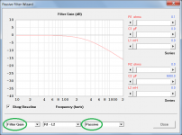
Hi six7one,
Power cannot be entered using Eg, only voltage. The BP6 Wizard assumes a constant input voltage Eg. The Maximum SPL tool assumes a constant input power. It is not possible to replicate the action of the Maximum SPL tool using the BP6 Wizard.
For the purpose of the exercise assume that you want to simulate a BP6 system with four drivers connected in a 2P2S arrangement, with each driver having two identical voice coils connected in series, and the manufacturer's specifications for one coil are Re = 6 ohms, Le = 2 mH and Bl = 15 T.m.
On the Hornresp main input screen specify:
Re = 12.00
Le = 4.00
Bl = 30.00
BP6 = 2P 2S
Then click the Wizard button.
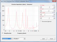
The simulation will be done using a constant voltage Eg at all frequencies. The actual resultant input power will vary considerably with frequency because the electrical input impedance of the BP6 system deviates greatly from the dc resistance value of Re = 12 ohms, as illustrated in the attached example.
If you want the driver dual voice coils to be connected in parallel rather than series, then on the main input screen specify:
Re = 3.00
Le = 1.00
Bl = 15.00
BP6 = 2P 2S
Kind regards,
David
Because I am using the BP6 driver arrangement I have been entering the power in Eg similar to the way it would be (I believe) entered in the maximum spl tool.
Power cannot be entered using Eg, only voltage. The BP6 Wizard assumes a constant input voltage Eg. The Maximum SPL tool assumes a constant input power. It is not possible to replicate the action of the Maximum SPL tool using the BP6 Wizard.
Given your above example I am assuming I can change the Re of the driver so long as I change the relevant parameters (Le and Bl) to reflect the change in Re? This should make modeling the dvc drivers easier if I am assuming this aspect correctly.
For the purpose of the exercise assume that you want to simulate a BP6 system with four drivers connected in a 2P2S arrangement, with each driver having two identical voice coils connected in series, and the manufacturer's specifications for one coil are Re = 6 ohms, Le = 2 mH and Bl = 15 T.m.
On the Hornresp main input screen specify:
Re = 12.00
Le = 4.00
Bl = 30.00
BP6 = 2P 2S
Then click the Wizard button.
The simulation will be done using a constant voltage Eg at all frequencies. The actual resultant input power will vary considerably with frequency because the electrical input impedance of the BP6 system deviates greatly from the dc resistance value of Re = 12 ohms, as illustrated in the attached example.
If you want the driver dual voice coils to be connected in parallel rather than series, then on the main input screen specify:
Re = 3.00
Le = 1.00
Bl = 15.00
BP6 = 2P 2S
Kind regards,
David
Attachments
Thank you David,
Your posts have clarified what I need to do to model my drivers correctly.
I have been reading that the Le value affects the high frequency range/response of a driver. If the concern of the frequency range is 80hz and below does the Le value affect much in terms of response predictions?
I ask this because sometimes, without having the driver, the Le value is unavailable from the manufacturer.
Hi six7one,
Assume 1 millihenry if the actual value of Le is unknown. Low frequency results are normally relatively insensitive to reasonably large changes in Le. Check that this is the case for your design by simulating using Le = 0.10, Le = 1.00 and Le = 10.00 and comparing the results. (For dual-coil drivers the above test values of Le should be halved if the coils are connected in parallel, and doubled if they are connected in series).
Kind regards,
David
If the concern of the frequency range is 80hz and below does the Le value affect much in terms of response predictions?
I ask this because sometimes, without having the driver, the Le value is unavailable from the manufacturer.
Assume 1 millihenry if the actual value of Le is unknown. Low frequency results are normally relatively insensitive to reasonably large changes in Le. Check that this is the case for your design by simulating using Le = 0.10, Le = 1.00 and Le = 10.00 and comparing the results. (For dual-coil drivers the above test values of Le should be halved if the coils are connected in parallel, and doubled if they are connected in series).
Kind regards,
David
Hornresp Update 3970-160527
Hi Everyone,
Information on dual voice coil drivers has been added to the Hornresp Help file, prompted by the recent posts from 'six7one' seeking clarification on how such drivers should be specified in Hornresp. My thanks to 'six7one' for raising the issue.
Kind regards,
David
Hi Everyone,
Information on dual voice coil drivers has been added to the Hornresp Help file, prompted by the recent posts from 'six7one' seeking clarification on how such drivers should be specified in Hornresp. My thanks to 'six7one' for raising the issue.
Kind regards,
David
Attachments
David,
I'm glad I was able to contribute even the tiniest to this amazing program. I wanted to add that after your posts I have been able to successfully manipulate the parameters properly for dual voice coil drivers. The 2S2P arrangements now show what looks like expected responses from dual voice coil drivers. The Eg subject has also been solidified, for me, as to how it is used and applied.
Many thanks.
Hi six7one,
Hornresp has benefited greatly from user contributions. It would not have evolved the way that it has without such inputs.
Excellent!
You're welcome.
Kind regards,
David
I'm glad I was able to contribute even the tiniest to this amazing program.
Hornresp has benefited greatly from user contributions. It would not have evolved the way that it has without such inputs.
I wanted to add that after your posts I have been able to successfully manipulate the parameters properly for dual voice coil drivers. The 2S2P arrangements now show what looks like expected responses from dual voice coil drivers. The Eg subject has also been solidified, for me, as to how it is used and applied.
Excellent!
Many thanks.
You're welcome
.Kind regards,
David
David,
I wanted to ask if there is any way to get the old colors (black background, etc.) for the wave simulator back?
The new yellow background with the near invisible point source pixel color has made it harder to outline the enclosure and wave points.
Thank you kindly.
I wanted to ask if there is any way to get the old colors (black background, etc.) for the wave simulator back?
The new yellow background with the near invisible point source pixel color has made it harder to outline the enclosure and wave points.
Thank you kindly.
I wanted to ask if there is any way to get the old colors (black background, etc.) for the wave simulator back?
The new yellow background with the near invisible point source pixel color has made it harder to outline the enclosure and wave points.
Hi six7one,
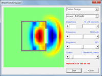
The colour scheme was changed to more clearly show sound pressure variations in the wavefronts. On my display monitor the driver source is bright white, the walls are grey and the zero pressure background is green. Do you see these same colours? Increasing the Brightness slider setting from the default 50% might perhaps make things a bit clearer.
I would prefer not to have to revert to the old duo-chrome red / green wavefront colour scheme, if at all possible.
Kind regards,
David
Attachments
- Home
- Loudspeakers
- Subwoofers
- Hornresp