Hi, must be wrong !
Hi Zero D,
Don't forget, the driver being used is 30 inches in diameter
") .
.Kind regards,
David
Hi Mike,
It doesn't matter either way, as far as the simulations are concerned.
Try simulating in Hornresp.
Try simulating in Hornresp.
Kind regards,
David
Would it be easier to not bifurcated,
It doesn't matter either way, as far as the simulations are concerned.
if this is a compound horn would it be better to have both horns the same length?
Try simulating in Hornresp.
Also, would it be best to have a rear chamber, as to get both horns in phase.
Try simulating in Hornresp.
Kind regards,
David
I have tried every way I know of to copy the window of hornresp with the results to this forum...but no luck...
Hi Mike,
The method I use is to:
1. Click on the Hornresp form to ensure that it has the focus.
2. Press the Alt+Prt Scr keys to copy the form to the Clipboard.
3. Paste the image from the Clipboard into Microsoft Paint.
4. Save the Microsoft Paint image as a .png picture file.
5. Click the diyAudio 'Manage Attachments' button in the 'Additional Options' section.
6. Click the 'Browse' button.
7. Select the saved .png picture file.
8. Click the 'Upload' button.
9. After the file is uploaded click the 'Close this window' button.
Kind regards,
David
Hi Kees,
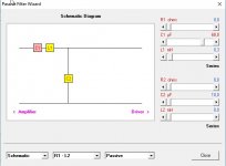
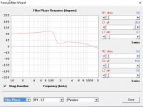
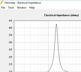
I would be interested in looking at this hornresp record effect on delay (normalized ^^), impedance. Would you mind to share it ? Do you still have the values used for the first thumbmail network filter ?
Thanks,
Damien
Attachments
-
 ScreenHunter_1060 May. 09 13.09.jpg31.9 KB · Views: 111
 -
tractrix-RECORD.zip507 bytes · Views: 28
-
 ScreenHunter_1066 May. 09 13.19.jpg47.5 KB · Views: 101
 -
 ScreenHunter_1064 May. 09 13.17.jpg19.9 KB · Views: 104
 -
 ScreenHunter_1063 May. 09 13.14.jpg46.3 KB · Views: 116
 -
 ScreenHunter_1062 May. 09 13.12.jpg57 KB · Views: 115
Hi Kees,
It is difficult to provide a definitive comment without knowing the actual input parameter values for the loudspeaker system in question. I am however reasonably confident that the simulation results are being correctly calculated. Note that if the same passive filter network is applied to the default record, the effect on the response is quite different. This is because the speaker frequency-dependent electrical input impedance loading the filter network is different.
Kind regards,
David
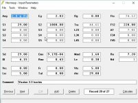
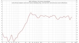
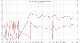
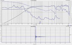
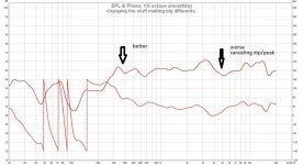
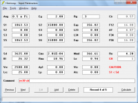
Hi David, in previous post I have some info, I did discover that when using higher compression in a horn, it get more allergic for passive filtering, so a high compression wideband horn do act with giving smaller bandwidth, when using a horn with a throat equal to the Sd of speker do act nicely when using passive xover.
I did saw in past that a tapped horn on a passive xover do also have bad respons, these need a amp and electronic crossover, also here because of higher compression of throat. This way I learn more so I do experiment a lot, I have now make a measurement with a wideband speaker in a horn with 3,5 x 3,5 cm throat and a adaptor, square to round..
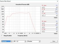
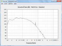
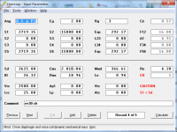
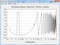
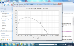
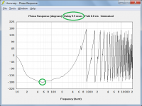
Here the sims is with a gap between speaker and horn throat and heavy damping between, (under carped if I write this right). You see the dip 4,5 Khz on picture three is moved to 15Khz when playing with it. and the fase get better also. in picture four, after adjust the gap damping the peak on 300 hz is much better, nice tests.
Attachments
Last edited:
Panel width?
I would like to sim some drivers using a proven design (Othorn) and play with the panel width. Which parameters do I adjust to change the width value?
Here are the original parameters in Hornresp.
http://i828.photobucket.com/albums/zz205/Kallus42/21SW152/OTHORNHRinput.jpg
Thanks
I would like to sim some drivers using a proven design (Othorn) and play with the panel width. Which parameters do I adjust to change the width value?
Here are the original parameters in Hornresp.
http://i828.photobucket.com/albums/zz205/Kallus42/21SW152/OTHORNHRinput.jpg
Thanks
David et all
Something seems wrong, it was too easy. Here are the forms from hornresp. Could somebody with more experience in this help me get my low corner up by tweaking something, if possible?
I wonder why it says "caution s1<sd", I got s1 by simulating just the driver in a normal horn so I thought it must be a good ratio.Does this mean I need a throat chamber?
Thanks
Mike
Attachments

David
I made the ratio lower, but still have "warning s1<sd", but it fixed my dip in low corner. I have this weird phase shift thing happening, is this something that's going to be a problem?
thanks
Mike
I made the ratio lower, but still have "warning s1<sd", but it fixed my dip in low corner. I have this weird phase shift thing happening, is this something that's going to be a problem?
thanks
Mike
Attachments
I would like to sim some drivers using a proven design (Othorn) and play with the panel width. Which parameters do I adjust to change the width value?
Hi brookhart995,
Hornresp is only interested in cross-sectional areas and axial lengths along the acoustic path.
1. If by panel width you mean panel thickness, then this not a Hornresp input parameter. Hornresp does not know or care how thick the horn wall panels are, it just assumes that they are completely rigid, and that they do not vibrate or resonate in any way.
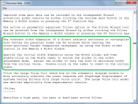
2. If however by panel width you mean the distance between the two parallel sides of a rectangular horn, then see the part of the Loudspeaker Wizard section in the Hornresp Help file highlighted in the attachment.
Kind regards,
David
Attachments
I did saw in past that a tapped horn on a passive xover do also have bad respons,
Hi Kees,
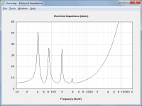
This is probably because the electrical impedance of a tapped horn has multiple peaks, making it a difficult load for a passive filter.
Kind regards,
David
Attachments
I made the ratio lower, but still have "warning s1<sd", but it fixed my dip in low corner. I have this weird phase shift thing happening, is this something that's going to be a problem?
Hi Mike,
1. The S1 < Sd cautionary note is just a reminder that a throat chamber really needs to be included in the simulation to account for the driver diaphragm being larger than the horn throat.
2. The "weird phase shift" is simply due to wrapping at 180 degrees. If you wish, the default-calculated delay value can be increased a little to remove the wrapping at that point. It's just an appearance thing - there's nothing to worry about
.Kind regards,
David
Attachments
Multiply your values of S1 to S....Where in Hornresp do you apply the correction factor? I am pretty new to this and cannot find it.
For example:
You have S1 of 1000cm²
Your known width of the horn is 100cm. So height of the start of the first hornsegment must be 10cm² (10cmx100cm=1000cm²)
You know want to make the horn wider ("play with the panel width"). Lets say, you want to go for 150cm² instead of the given 100cm² (=value of S1).
So 150cm x 10cm = 1500cm² -> new value of S1 = 1500cm²
1500 / 1000 = 1.5 <- this is your "correction factor".
Simply multiply all S-Values by 1.5.
Now you have the S1 to S... Segments with new area values which correspond to your new horn with a new width of 150cm instead of the original with 100cm.
"correction factor" is not a function in hornresp or a switch.. its just my term for the factor you have to multiply your area values with
Addition: Maybe I understood wrong what you wanted. David mentioned it above... If you want to use different "thickness of wood", you have to do the math by yourself. If you simply want to make the box "wider" than Davids suggestion is of course the most elegant way which basically does what I illustrated (my way was "by hand"..)
Last edited:

How should I model this?
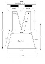
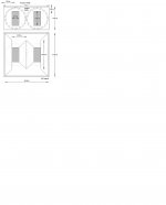
Wondering how to model this midbass horn. There are two drivers, so Nd=2, and they are "normal" parallel.
I'm thinking it should be done in two sections:
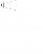
Second section has S3=36x36", S2=24x24", and L23=24"
How about the first section? S1=2x5.75"x12"? and L12=24"
So what about the drivers? Sd would be that of a single driver, like the T/S parameters. Vtc and Atc would be that of the two drivers added?
Aand the rear chamber volume would be of the combined chamber, or half that?
And for a horn playing from 80 to 400Hz and having its mouth sitting on the floor and 1.5m away from the front wall should I use 2*pi or 1*pi?
Wondering how to model this midbass horn. There are two drivers, so Nd=2, and they are "normal" parallel.
I'm thinking it should be done in two sections:
Second section has S3=36x36", S2=24x24", and L23=24"
How about the first section? S1=2x5.75"x12"? and L12=24"
So what about the drivers? Sd would be that of a single driver, like the T/S parameters. Vtc and Atc would be that of the two drivers added?
Aand the rear chamber volume would be of the combined chamber, or half that?
And for a horn playing from 80 to 400Hz and having its mouth sitting on the floor and 1.5m away from the front wall should I use 2*pi or 1*pi?
Attachments
You deserve a metal for all the selfless work and time you put into this forum, not to mention hornresp.
Thanks Mike
.- Home
- Loudspeakers
- Subwoofers
- Hornresp