Hi otter17,
Could you please post a copy of the Hornresp Input Parameters window for your design.
Kind regards,
David
Thank you david.

I have a question regarding a result I am getting when simulating a folded bass bin for a Kappa Pro 12a.
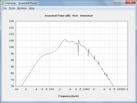
When simulating the same design in 2Pi the roll-off starts way later than simulating in 1Pi conditions. Why is that? I get that the bass should be boosted under such conditions and in relation, the lower mids would be attenuated... But here it just seems like the roll-off starts earlier, with only minimal extension of bass output if any. Where is my failure in understanding?
Hi otter17,
Thanks for providing the Input Parameters window screenprint.
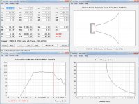
It just so happens that by sheer chance, with the very large throat chamber used in your design, when loaded by the horn radiating into 1 Pi space, the throat impedance becomes such that the low pass filter effect of the chamber proves to be very significant. (It seems that the size of the chamber has been specifically optimised for 2 Pi performance).
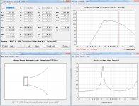
The attached screenprint shows the responses with the throat chamber removed, and the value of Eg changed to 4 volts for the 2 Pi case so that the high frequency response levels are directly comparable (in effect, the 2 Pi response has been lifted by 3 dB). As for your example, the grey trace is the 1 Pi response and the black trace is the 2 Pi response. Notice how without the throat chamber, the high frequency roll-offs are now essentially the same for both cases. At low frequencies the 1 Pi response is shown to be 3 dB higher than the 2 Pi response, as expected.
In general, when the value of Ang is changed from 2 x Pi to 1 x Pi the overall power response lifts by 3 dB because the space into which the sound power radiates has been halved. A further 3 dB is gained at low frequencies because of the improved LF acoustical loading conditions at the horn mouth.
Hope this helps to clear things up.
Kind regards,
David
Attachments
Last edited:
The value specified for Vrc should include the volume occupied by the lining material but exclude the volume occupied by the driver.
From the Help file: "The rear chamber volume is the effective enclosed air volume behind the driver diaphragm, including any space occupied by acoustical lining material but excluding port tube, driver magnet and chassis assemblies."
For example, a square box with internal dimensions of 10cm x 10cm x 10cm, lined with absorbent material, would have a Vrc value of 1 litre.
Kind regards,
David
Thank you. Moving along with the rear chamber contruction.
One aspect that concerns me is beam width match to the tweeter. The tweeter has a 80°x30° waveguide that works as designed, so at the xo point (2500Hz) beam width is 80°. The horn I'm coming up with has a beam width of 48° at 2500Hz, and I'm having trouble figuring out a way to increase it. I believe shorter horns lead to wider dispersion at higher frequencies, but when I try to do this on Hornresp I can't figure out how to model that. How do you suggest I increase BW at 2500Hz to 80° or so?
Attachments
Hi LewinskiH01,
The Hornresp beam width figure applies to an axisymmetric horn, not a rectangular horn.
Use a conical width flare, similar to the configuration shown in Attachments 4 to 6 in Post #6190.
Kind regards,
David
The horn I'm coming up with has a beam width of 48° at 2500Hz,
The Hornresp beam width figure applies to an axisymmetric horn, not a rectangular horn.
How do you suggest I increase BW at 2500Hz to 80° or so?
Use a conical width flare, similar to the configuration shown in Attachments 4 to 6 in Post #6190.
Kind regards,
David
An excellent performing example: retro vintage modern hi-fi: RCA Theater Bass Horn Ubangi or MI-9462
GM
GM
An excellent performing example: retro vintage modern hi-fi: RCA Theater Bass Horn Ubangi or MI-9462
GM
Interesting. Do you believe the 40Hz it is reported to work to are coming from the vertical slots at the sides, in turn linked to the back of the woofers?
If the front-loaded bass horn can get to 80Hz smoothly, then I'm interested. The sides seem to have a straight conical profile and the top/bottom radial. And more interesting, the radial isn't starting horizontally, but rather further away from the woofer axis, then gets closer, then gets further away. So initially compression, later expansion.
At lower frequencies I'd think there is an overall expansion, and running the sides out in this conical style with some horn profiles will result in a top/bottom that close up just beyond the throat. I think herein lies the interesting thing about non-axissymmetric horns insofar as separating loading and waveguiding aspects.So initially compression, later expansion.
running the sides out in this conical style with some horn profiles will result in a top/bottom that close up just beyond the throat.
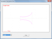
Exactly as shown in Attachment 6 in Post #6190, reproduced below. The horizontal dimension increases rapidly near the throat due to the conical width flare profile, requiring the vertical dimension to be reduced to maintain the necessary overall tractrix area expansion.
Attachments
David I really appreciate you showing the different aspects of how your program works.
Hi Mark,
Not a problem - it's all just part of the ongoing "Hornresp User Support Service"
") .
.Kind regards,
David
User interface suggestion...
David,
1'st...I've thanked you before for all of your wonderful work...and now I'm going to make a suggestion (ask for something) so I feel compelled to thank you again.
Thank you.
So....a suggestion...there's a ton of wonderful plots that are available and I find myself looking between them often. Displacement, acoustical and electrical impedance, maximum output, throat velocity etc and back to the input screen....but each time to switch back and forth requires the use of shortcut keys and or several mouse clicks. Is it possible to tile the most often used ones in a larger display so that all of them are shown.
Back in the day there was limitation in screen resolution, memory etc...but that probably isn't that big of an issue.
The reason I bring it up is every once and a while my repetitive stress issues creep up and I have to limit my number of clicks and on a computer. I have to save them for work and I can't speaker-stuff as much as I'd want.
Scott
So....a suggestion...there's a ton of wonderful plots that are available and I find myself looking between them often. Displacement, acoustical and electrical impedance, maximum output, throat velocity etc and back to the input screen....but each time to switch back and forth requires the use of shortcut keys and or several mouse clicks. Is it possible to tile the most often used ones in a larger display so that all of them are shown.
The reason I bring it up is every once and a while my repetitive stress issues creep up and I have to limit my number of clicks and on a computer.
Hi Scott,
Thanks for the suggestion - unfortunately it would require a major re-build to implement the feature. It is not something that I am in a position to take on.
With regard to the default result windows, probably the easiest way to navigate through them is to press the F2 function key to move from one window to the next, or to press the Esc key to return to the Input Parameters window from any result window. If this method is used, no mouse clicks are required.
With regard to the secondary chart windows (particle velocity, etc) each is generated on demand, so there is no way to quickly navigate from one to the other.
Kind regards,
David
David, I'm thinking about how to get data on a horn that starts OS and finishes Lecleach. (Edit, in some respects a multiple conical sim may self answer some of these questions)
If the throat impedance might be reasonably indicative if I model the initial OS section (ignoring the Lecleach section) and have it behave as if it almost doesn't terminate..
1. Is a finite horn normally modelled as if there is a mouth reflection that is tied to the indicated loading space.
2. Will 0.5pi achieve this for a near or slightly less than 90 degree conical?
3. Is 'infinite' loading also appropriate or is there a difference?
4. Would it be reasonable to assume I could estimate (approximate) the directivity by manually combining these two models?
5. Is there a way to model a driver that represents the output of the OS section to feed the Lecleach? (The overall acoustic output might not be so essential but I'd like an estimate of group delay (absolute value is not important just the variations) unless there is another way to go about it, even I suppose if I have to exclude GD variations produced by the driver itself).
Last edited:
David, I'm thinking about how to get data on a horn that starts OS and finishes Lecleach.
Hi AllenB,
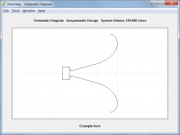
About the only thing you could do in Hornresp would be to specify a conical throat chamber as shown in the attachment. While not an OS waveguide, it might give an indication of the performance that you could expect to see. Note that the Le Cléac'h horn has to be a certain minimum length (which may be longer than you want).
If the reason for having the Le Cléac'h segment is simply to reduce mouth reflections, then I guess the system could be modelled as an infinite OS waveguide.
Otherwise, I can't see any way of obtaining meaningful results using Hornresp.
Kind regards,
David
Attachments
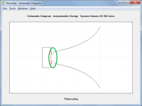
Serendipity had it. I was playing around with Hornresp to understand the impact of minor changes I was considering to the tractrix midrange, when I inadvertently increased S1 from Sd/2 to 90% of Sd, but neglected to change Atc to the same value...and found a very extended high range.
Attached is the model. How would I build this in actuality, though? Is the reduced Atc with larger S1 how one would model a phase plug?
Attached is the model. How would I build this in actuality, though? Is the reduced Atc with larger S1 how one would model a phase plug?
Attachments
How would I build this in actuality, though?
Some sort of adaptor or transition piece would be required between the driver diaphragm and the throat chamber to reduce the area from Sd down to Atc.
(Also, the abrupt change from Atc to S1 is not good practice).
Is the reduced Atc with larger S1 how one would model a phase plug?
Not really.
Some sort of adaptor or transition piece would be required between the driver diaphragm and the throat chamber to reduce the area from Sd down to Atc.
(Also, the abrupt change from Atc to S1 is not good practice).
Not really.
Have you seen a successful implementation of something like the above? Is it worth exploring, or would it basically be a waste of time?
How should I model a phase plug?
Notes
To a first approximation, simply model it with a very small front cavity volume that you can get by introducing a phase plug. N.B.: the first part of the horn throat expansion is implemented by the phase plug passages. Here you simply model them with an extension of the horn throat to the desired [St]. What you will be overlooking at this point, are details concerning chamber standing wave modes and wave-front shape in the throat region of the horn. To get to CD behavior the OS expansion in the throat area is most important. To understand phase plug design issues, study the work of Smith, Geddes, and Dodd. WHG
Have you seen a successful implementation of something like the above? Is it worth exploring, or would it basically be a waste of time?
How should I model a phase plug?
To a first approximation, simply model it with a very small front cavity volume that you can get by introducing a phase plug. N.B.: the first part of the horn throat expansion is implemented by the phase plug passages. Here you simply model them with an extension of the horn throat to the desired [St]. What you will be overlooking at this point, are details concerning chamber standing wave modes and wave-front shape in the throat region of the horn. To get to CD behavior the OS expansion in the throat area is most important. To understand phase plug design issues, study the work of Smith, Geddes, and Dodd. WHG
Have you seen a successful implementation of something like the above?
No, not personally.
Is it worth exploring, or would it basically be a waste of time?
I suspect that it would be difficult to achieve a measured response as good as the prediction shown in your simulation.
How should I model a phase plug?
Specify using Vtc, Atc, Ap1 and Lp. The air space between the diaphragm and the phase plug is modelled using throat chamber Vtc / Atc and the phasing air passages are modelled using throat adaptor Ap1 / Lp, as shown in the attachment.
Attachments
Last edited:
- Home
- Loudspeakers
- Subwoofers
- Hornresp