Hi oriaM,
As Nd= 2S:
1. = 55
2. = 55
3. = No
b")
Correction: 2. Should be 110, not 55!b
@ bjorno,
I would expect a difference of at least 3 dB.
Why don't I see this difference?
If supplied from a constant Eg:2 Drivers in series consumes half the power so the + 6dB SPL gain from doubling the Sd is lost as both drivers gets only a 1/4 of the power each i.e. -3dB will be added to the SPL compared to when using one driver.
b
Last edited:
The power compression model seems to only take account of the increased resistance due to the temperature rise.
Is there any audible, or measurable, effect due to added distortion when the temperature cycles during each half cycle of the peak signal?
i.e. dynamic changes in the VC resistance will give distortion of the output.
This would be roughly equivalent to "soft clipping" of the lower frequencies (with respect to the time constant of the VC).
Sure, if you put in huge peaks to your driver, I'm sure you would see distortion. I'm not sure you could easily differentiate what was due to just thermal compression without doing a lot of measuring and modeling of the driver. Ie, if you put a big peak in, the coil will quickly heat up, changing the Re. But it will also move. This will change the BL, CMS, and Le among other things depending on the design of the driver and the signal applied. All those things will cause distortion as well.
Typically you will have several thermal time constants in a driver / speaker system. The coil will typically have a very short time constant which can cause the dynamic compression you're talking about. But the coil will transfer heat to the pole piece and top plate, heating them up. Those will transfer heat to the magnet, frame, surrounding air, etc. All that takes longer. All those pieces are also much larger and have much longer thermal time constants. How hot they are also effects the voice coil. Ie, if you play continuous loud content for 5 hours and heat the entire system up, even if you then stop playing music, the voice coil will still be warm and have a higher Re because the surroundings are warm.
Looking at the response when the coil is hot gives you an idea how your frequency response will look after it has been heated up on a long term basis. Ie, your sensitivity drops a bit and you get more of a bump around driver resonance, or something like that. You know that you'll still have short term effects from power compression as well, just like you know you'll have distortion from the motion of the coil in the motor, distortion from the air in the front and back chamber being compressed, etc. But it's tough to model that power compression without a very detailed model of the driver. It's the same reason that Hornresp doesn't predict distortion of the entire horn at a certain level.
Hiya folks
Sorry if im posting in the wrong forum thread, mods please delete/move if so.
My question is in relation to a mid horn design im working with on hornresp, I understand hornresp is not very accurate at this, im using it more to fine tune the low extention of the horn, not the upper response.
Anyway my problem is when im checking max spl relating to xmax limit, i need to far exceed the power the VC can handle. i.e. i need to turn up EG 4 x the power limit of the driver.
the driver in question is Eminence Kappa Pro 10A - 500W.
The horn design is 70cm long, 100cm2 throat, 3700cm2 mouth.
simulation max spl - 135dB at 3.2 mm xmax, RMS voltage (EG in hornresp) at this spl is 126.5 Volt or 2000 Watt!!!
is this normal for hornresp when designing mid horns or am i going very wrong. any help would be greatly appreciated.
cheers
thanks. but i always been told hornresp becomes less accurate the higher the frequency, hence the roll off higher up the response graph.
anyway heres the hornresp record:
ID=34.20
Ang=4.0 x Pi
Eg=126.49
Rg=0.00
Fta=28.60
S1=100.00
S2=100.00
Con=3.60
F12=0.00
S2=100.00
S3=298.00
Con=25.00
F23=0.00
S3=298.00
S4=3690.00
Con=45.00
F34=0.00
S4=0.00
S5=0.00
L45=0.00
F45=0.00
Sd=345.00
Bl=18.80
Cms=3.08E-04
Rms=1.14
Mmd=36.92
Le=1.00
Re=6.50
Nd=1
Vrc=3.00
Lrc=16.00
Fr=0.00
Tal=0.00
Vtc=900.00
Atc=350.00
Pmax=100
Xmax=5.0
Path=0.0
Fr1=0.00
Fr2=0.00
Fr3=0.00
Fr4=0.00
Tal1=100
Tal2=100
Tal3=100
thanks for the reply by the way!
Last edited:
More10 - yes sorry i do believe im using an outdated version of hornresp, i just havent been bothered to download the latest version as ive not come across any bugs in the one im using. And i apologise for hogging space, didnt realise i can condense it into an attached file :S
Tb46 - unfortunately i cannt view your file as im using a mobile device at the moment but will take a look once im on a computer. In regards to the high excursion below ~200hz; there will be a high pass filter in use at circa 190 hz (24dB butterworth) which should curb that high excursion you mentioned down to the 3.2mm recommended xmax level. This can been seen in the: tools-->filter wizard, if i remember correctly
Alas i still have the same problem that to reach aforesaid xmax limit i must apply excessive voltage/power to driver, namely 4 x the recommended limit for the driver (126.5v or 2000w!).
Any anyone explain why this might be the case? Is it because im using an older vetsion of hornresp?
I would be eternally greatful to anyone who could enlighten me.
Regards.
Last edited:
Hi SillySounds,
It is important to differentiate between the acoustical power response, which is calculated by default, and the acoustical pressure response, which requires the use of the Directivity tool and is limited to single segment horns.
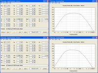
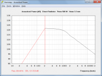
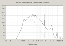
To illustrate the difference, Attachment 1 compares the power response for your design (grey trace), against the on-axis pressure response (black trace) for an effectively equivalent single segment exponential horn, where S1 = 100, S2 = 3690 and L12 (Exp) = 73.6.
Attachment 2 compares the power response for your design (grey trace) against the power response for the equivalent single segment exponential horn used to calculate the above directivity response (black trace). As you can see, the results are effectively the same.
You have not included the complete record - the Tal4, Comment, and Filter fields are missing.
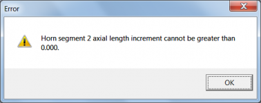
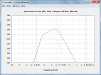
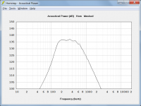
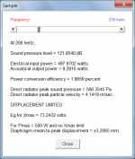
Pmax = 500 W and Xmax = 3.2 mm assume that the driver is being used as a direct radiator, as shown in Attachments 3 and 4. Horn loading the driver with a Sd / S1 compression ratio of 3.45:1 as you have done, will significantly reduce the diaphragm displacement for a given input power.
No.
Kind regards,
David
but i always been told hornresp becomes less accurate the higher the frequency, hence the roll off higher up the response graph.
It is important to differentiate between the acoustical power response, which is calculated by default, and the acoustical pressure response, which requires the use of the Directivity tool and is limited to single segment horns.
To illustrate the difference, Attachment 1 compares the power response for your design (grey trace), against the on-axis pressure response (black trace) for an effectively equivalent single segment exponential horn, where S1 = 100, S2 = 3690 and L12 (Exp) = 73.6.
Attachment 2 compares the power response for your design (grey trace) against the power response for the equivalent single segment exponential horn used to calculate the above directivity response (black trace). As you can see, the results are effectively the same.
anyway heres the hornresp record:
You have not included the complete record - the Tal4, Comment, and Filter fields are missing.
Alas i still have the same problem that to reach aforesaid xmax limit i must apply excessive voltage/power to driver, namely 4 x the recommended limit for the driver (126.5v or 2000w!).
Pmax = 500 W and Xmax = 3.2 mm assume that the driver is being used as a direct radiator, as shown in Attachments 3 and 4. Horn loading the driver with a Sd / S1 compression ratio of 3.45:1 as you have done, will significantly reduce the diaphragm displacement for a given input power.
Is it because im using an older vetsion of hornresp?
No.
Kind regards,
David
Attachments
Last edited:
Thank you very much Mr Mcbean, it seems I have very much to learn in respect to using hornresp.
Im afraid that I'm struggling to understand the real difference between acoustical power and acoustical pressure. Would you have any reading/an explanation that could help me understand the basics of what is happening on the simulation, and how acoustical power and acoustical pressure responses corralate to form a good impression of what the real life horn may play?
And what your saying is that the fact 500w and 3.2 mm xmax is assuming a direct radiating transducer, and hornloading the driver would reduce the xmax figure for a given spl. Thanks for explaining that, gives me a better impression of where im going wrong!
Sorry to be asking such questions to yourself, as your most likely not interested in my design, being here more for technical questions about hornresp itself. Please accept my apologises for this.
Thank you again for your time and thank you for designing such a useful program!
P.S. I have attached a file with the updated hornresp simulation parameters for my design. I hope this will give a better impression of what im trying to do
Regards.
Attachments
The acoustical power is the total energy the horn radiates. If you measured at many points around the horn with a microphone, you could then calculate the acoustical power. However most horns have at least some directivity - the sound power is not evenly distributed over all angles. So the directivity tools in Hornresp allow you to try to predict how the horn will direct the sound - typically at very low frequencies, the horn will radiate evenly everywhere (omnidirectional) and as frequency increases, the horn will have an increasingly narrow beam of sound. Exactly what frequencies these are depend on the size of the horn. In terms of understanding how this relates to what you hear, if you were outside far from any reflections or in an anechoic chamber with your horn, you would only care about the pressure response where you wanted to listen (typically on axis). If you are in a room, what you hear will be a combination of the power response and the direct response (on axis or some other axis that is pointed towards you). With a very directive horn in a very dead room, you will hear more of the direct sound and less of the power response, and vice versa. If you are building a low frequency device, the modal response of the room and where you position the speaker will have a very strong effect on what you hear.
Hi SillySounds,
I am sure that everything will become a lot clearer soon enough - "practice makes perfect".
John has provided an excellent explanation in his post above. Try Googling 'difference between acoustic power and pressure' or similar, if further details are required.
Just to clarify - horn loading the driver does not reduce the Xmax figure (the driver displacement limit specified by the manufacturer). What it does do, is to reduce the driver diaphragm displacement for a given SPL, which is what I think you meant to say.
Note that even though horn loading may allow more power to be delivered to the driver without exceeding Xmax, it is likely that Pmax will be exceeded, which probably means that the voice coil is heated to such a temperature that a failure could occur.
You have nothing to apologise for.
As far as I am concerned we have been discussing how Hornresp can assist with the design process in general, not with your specific design.
You're welcome.
Thanks. Note that the Comment field can be edited, and the default "NEW RECORD" words deleted, if so desired.
Kind regards,
David
it seems I have very much to learn in respect to using hornresp.
I am sure that everything will become a lot clearer soon enough - "practice makes perfect"
.Would you have any reading/an explanation that could help me understand the basics of what is happening on the simulation, and how acoustical power and acoustical pressure responses corralate to form a good impression of what the real life horn may play?
John has provided an excellent explanation in his post above. Try Googling 'difference between acoustic power and pressure' or similar, if further details are required.
and hornloading the driver would reduce the xmax figure for a given spl.
Just to clarify - horn loading the driver does not reduce the Xmax figure (the driver displacement limit specified by the manufacturer). What it does do, is to reduce the driver diaphragm displacement for a given SPL, which is what I think you meant to say.
Note that even though horn loading may allow more power to be delivered to the driver without exceeding Xmax, it is likely that Pmax will be exceeded, which probably means that the voice coil is heated to such a temperature that a failure could occur.
Sorry to be asking such questions to yourself, as your most likely not interested in my design, being here more for technical questions about hornresp itself. Please accept my apologises for this.
You have nothing to apologise for
.As far as I am concerned we have been discussing how Hornresp can assist with the design process in general, not with your specific design.
Thank you again for your time and thank you for designing such a useful program!
You're welcome
.P.S. I have attached a file with the updated hornresp simulation parameters for my design. I hope this will give a better impression of what im trying to do
Thanks. Note that the Comment field can be edited, and the default "NEW RECORD" words deleted, if so desired.
Kind regards,
David
John Sheerin - I see. So to get a good idea of what the horn may play, I would have to take both the power response and pressure response into account, but also bearing in mind that different environmental factors will also affect the low frequency responce. Thanks for that explaination, I have now looked into my simulations and cross-referenced between them to get a better idea of what they might play.
Although i wanted to ask, since in the power response is the total energy radiated from the horn (and at low frequency bass is omni-directional), this does not give a good idea of the actual low frequency response (assuming outdoor use, i.e. no room modes/nodes, constructively/destructively augmenting the response). In reality the directional pressure response in hornresp gives a more accurate idea of what you might hear the horn play, in the low register, as stood in a single spot you wouldn't hear the total low frequency energy, only the energy radiated in your immidiate area (sorry, this isn't a good explaination. I hope it's coming across as understandable) . Am I correct in assuming this?
David McBean - Firstly, your are correct with "practice makes perfect", the help you and John have provided, has opened a whole new chapter in my 'hornresp journey'
And yes when I said "hornloading the driver would reduce the xmax figure for a given spl", I did indeed mean reducing driver displacement, glad that it came across okay though. Sometimes being a relative newbee in this game, a lot of the terminoligy does still confuse.
Anyway I do intend to mount a metal plate (alumininum preferably, although anything that is to hand is probably the more likely haha) on the rear of the back chamber, to act as a heat-sink. Hopefully this will allow for more input power and less power compression.
I am aware that the comment field can be edited, it is just when im siming with a specific driver I tend to compare a lot of different sims to find the most efficient design parameters, so theres too many (or I'm just too lazy) to give them individual names. Thanks for the heads up anyway though.
Regards.
In reality the directional pressure response in hornresp gives a more accurate idea of what you might hear the horn play, in the low register, as stood in a single spot you wouldn't hear the total low frequency energy, only the energy radiated in your immidiate area
Maybe - it depends on the horn and what 'low frequency' is. If you use the horn outdoors in a frequency range where it has no directivity, then the power response should be the same as the pressure response on-axis. If the horn has directivity in the frequency range you're using it in, then you are correct - the pressure response would be a better prediction.
For example, say I make an 80Hz horn and simulate it in 4pi space (free field). Below about 100Hz, it's omni and the power response and 0 degree pressure response are the same. But those two curves deviate from each other more and more the higher in frequency you go.
Attachments
- Home
- Loudspeakers
- Subwoofers
- Hornresp