David McBean said:
Hi GM,
It is not possible for Hornresp users .... to choose a different data file to load.
It is possible
Bjørn Kolbrek wrote this nice little program called hornrespmerge
hornrespmerge
David McBean said:
You must be the only person in the world to have 999 records in Hornresp.
Greets!
Actually, I ran out quite awhile back, deleting a bunch on several occasions. Lately, I've just been writing over them, but at some point I'm going to be down to a core driver database, so thought I'd ask.
Since I calc most designs, it's just a matter of inputting the results, so don't have that much time invested in them. The sheer quantity is due to the inverse square rule of the less you charge, the exponentially faster your 'business' grows, so doing sims at no charge, my email Inbox is never empty, though it has tapered off a bunch since you added the slider TH Wizard.
GM
AndrewT said:buy a second PC.
or install hornresp in another folder.
I get enough grief from one, so don't want to 'double my trouble'.
Computers aren't my 'thing', so will this work, or is this a 'tongue-in-cheek' remark?
GM
jogi59 said:
Bjørn Kolbrek wrote this nice little program called hornrespmerge
Thanks, I downloaded it awhile back just in case I ever needed it, but didn't consider it would be of any use for my situation, though if I can have multiple HR program folders, then this should allow me to export/segregate by type, i.e. TLs, FLHs, etc.. Then the only downside is I can't run but one folder at a time.
Or, since I have multiple partitioned HDs, if I put the folders in separate partitions can I run them simultaneously?
GM
GM said:Then the only downside is I can't run but one folder at a time.
Or, since I have multiple partitioned HDs, if I put the folders in separate partitions can I run them simultaneously?
Hi GM,
Hornresp requires that the Hornresp.dat data file be stored in a folder call 'Hornresp' located immediately beneath the root directory of the drive that the program is installed on.
If you have multiple Hornresp.dat files then about all you can do is to save them into individual archive folders and copy the file you require back into the program's 'Hornresp' folder when you wish to work with it.
Not an ideal situation, I agree, but I am reluctant to increase the data file record limit as operationally things would tend to become rather unwieldy. I suspect that very few users (apart from your good self) will ever get anywhere near the 999 limit anyway
") .
.Kind regards,
David
Hornresp Version 21.40
Hi Everyone,
I managed to find a few spare hours over the weekend. Hornresp can now calculate the impulse response for any horn loudspeaker system. Results are slightly different to those generated previously, but should be more accurate.
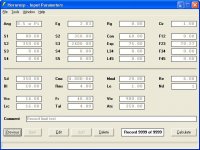
Also, the limit on the maximum number of data records has been increased to 9999 - hopefully this will be enough even for GM. With 9999 records, the Hornresp.dat data file size is 3526 KB.
Version 21.40 refers.
Kind regards,
David
Hi Everyone,
I managed to find a few spare hours over the weekend. Hornresp can now calculate the impulse response for any horn loudspeaker system. Results are slightly different to those generated previously, but should be more accurate.
Also, the limit on the maximum number of data records has been increased to 9999 - hopefully this will be enough even for GM
. With 9999 records, the Hornresp.dat data file size is 3526 KB.Version 21.40 refers.
Kind regards,
David
Attachments
Hornresp Version 21.50
Hi Everyone,
To make it easier to search for records in what now can potentially be a very large Hornresp.dat data file, a filter has been added to the Find tool. For example - to list all tractrix horn records select 'Tra' from the filter drop-down box, to list all tapped horn records select 'TH'.
Version 21.50 refers.
Kind regards,
David
Thanx a lot david, this comes in very handy!!!! As alway it´s a pleasure to see your ongoing support if the community with hornresp!!
I did some comparison to akabak and LSPCad regarding impulsresp.
A single TH with a 15":
Exportet to Akabak, I get this (time impuls, 0-40msec, normalized y-Axis):
Same but with time step:
Akabak is capable of looking at a cutout of the frequency range if only a small range is of interest (as with subs).. Same input data, but time step is derived from about 30 to 350 Hz:
Resolution of course is too low now, but raising the sim-points/oct gives more resolution in the iFFT calculation.
Comparing to another software:
doing a simple closed box with the default driver:
Thrown into LSPCAD:
LSPCAD couts of everything pre to 0ms and leaves out the distance between virtual mic/ears and the transducer, which results in a offset from a few ms to the left and the ommitance of the transient oscillation before 0msec.. But otherwise both results seems comparable.
Taking the same enclosure, just adding a port... before hitting the "compined" response, we get something quite similar to the closed box (which is plausible, except for the notch at the tuning frequency of the resonator, the box stays the same.. )
After adding the port response with "combined response":
Typical ported Box, seems ok.
Doing the same Box in LSPCad:
Same difference on time-axis as above wit the CB, otherwise the same except for the ripples which LSPCad simply seems to smooth out...
Looks good
I did some comparison to akabak and LSPCad regarding impulsresp.
A single TH with a 15":
An externally hosted image should be here but it was not working when we last tested it.
Exportet to Akabak, I get this (time impuls, 0-40msec, normalized y-Axis):
An externally hosted image should be here but it was not working when we last tested it.
Same but with time step:
An externally hosted image should be here but it was not working when we last tested it.
Akabak is capable of looking at a cutout of the frequency range if only a small range is of interest (as with subs).. Same input data, but time step is derived from about 30 to 350 Hz:
An externally hosted image should be here but it was not working when we last tested it.
Resolution of course is too low now, but raising the sim-points/oct gives more resolution in the iFFT calculation.
Comparing to another software:
doing a simple closed box with the default driver:
An externally hosted image should be here but it was not working when we last tested it.
Thrown into LSPCAD:
An externally hosted image should be here but it was not working when we last tested it.
LSPCAD couts of everything pre to 0ms and leaves out the distance between virtual mic/ears and the transducer, which results in a offset from a few ms to the left and the ommitance of the transient oscillation before 0msec.. But otherwise both results seems comparable.
Taking the same enclosure, just adding a port... before hitting the "compined" response, we get something quite similar to the closed box (which is plausible, except for the notch at the tuning frequency of the resonator, the box stays the same.. )
An externally hosted image should be here but it was not working when we last tested it.
After adding the port response with "combined response":
An externally hosted image should be here but it was not working when we last tested it.
Typical ported Box, seems ok.
Doing the same Box in LSPCad:
An externally hosted image should be here but it was not working when we last tested it.
Same difference on time-axis as above wit the CB, otherwise the same except for the ripples which LSPCad simply seems to smooth out...
Looks good
Hi David,
Thank you for your continuing improvements of Hornresp. The easy to use impulseresp tool is great. Could a "Compare Previous" button be added to this function?
And, the additional number of data records in combination with an improved find function is quite helpful.
Thanks again,
Regards,
Thank you for your continuing improvements of Hornresp. The easy to use impulseresp tool is great. Could a "Compare Previous" button be added to this function?
And, the additional number of data records in combination with an improved find function is quite helpful.
Thanks again,
Regards,
What is the reference for the impulse response calculation?
Hi Sabbelbacke,
Thanks for all the simulations.
Hi again David,
It seems that the impulse response curve is derived from the last SPL calculation, and not the particular driver plus enclosure combination in general. That means that it is really important to get the path length right for the combined response graph (e.g.: back-loaded horns).
I wonder if this is a feature or a bug?
Regards,
The phase and group delay plots in Hornresp still represent the response at the driver (useless) rather than the response being shown in the SPL graph, regardless of the way in which it was last calculated.
Could this be fixed? Couldn't phase and group delay be derived from the SPL plot every time it's calculated?
Could this be fixed? Couldn't phase and group delay be derived from the SPL plot every time it's calculated?
Sabbelbacke said:I did some comparison to akabak and LSPCad regarding impulsresp.
Hi Sabbelbacke,
Thanks for the comparisons, they are very interesting indeed. Jean-Michel calculates impulse response using a method different to AkAbak and LspCAD, so it is not surprising that there may be some variances in the results.
Kind regards,
David
tb46 said:Could a "Compare Previous" button be added to this function?
Hi Oliver,
See my post #471.
Kind regards,
David
Re: What is the reference for the impulse response calculation?
Hi Oliver,
In effect, yes.
Kind regards,
David
tb46 said:It seems that the impulse response curve is derived from the last SPL calculation.
Hi Oliver,
In effect, yes.
Kind regards,
David
Eva said:The phase and group delay plots in Hornresp still represent the response at the driver (useless) rather than the response being shown in the SPL graph, regardless of the way in which it was last calculated.
Could this be fixed? Couldn't phase and group delay be derived from the SPL plot every time it's calculated?
Hi Eva,
Sorry to hear that you consider some of the Hornresp results to be useless, and that they need fixing. If system phase and group delay charts were provided, how would you use this information? (Bearing in mind that the phase results would be shown in wrapped form).
Perhaps you could use AkAbak instead, if system phase and group delay are important to you?
Incidentally - the existing phase and group delay charts give an indication of the behaviour of a driver when horn loaded, and are also entirely relevant to a direct radiator loudspeaker system. The Hornresp results have been validated against data published by Marshall Leach.
Kind regards,
David
Knowing the actual phase and group delay of the SPL plot that is being shown is very important for sizing rear chambers for flatter group delay at lower cutoff and for crossover design, for designing horns allowing for easier phase matching (MF, HF). Propagation delay (either derived from horn length or just a value asked to the user) should be substracted for getting more meaningful phase plots without many wraps. Group delay should be meaningful without any adjustment.
The phase and group delay at the driver have little meaning because nobody is listening there, because the other drivers and horns the system is interacting with are not there (except in unity-like systems) and because the impedance ripple of the horn causes horrible phase and group delay ripple at the driver that does not actually appear at the horn mouth in most cases, it's just flattened through the horn.
In general the effective phase and group delay response in the bottom octave (after the horn) is quite different from shown in these plots.
Hello,
As David wrote, the method used to derive the pulse response in Hornresp is different. Specially IFFT is not used.
A discrete inverse Fourier transform based on a log scale of frequency as the one in Hornresp (533 frequency points) is used.
As I told to David, the initial hypothesis is a continuous spectrum. When both the SPL and phase spectrum in Hornresp are continuous, then the calculated pulse is perfectly correct (and we can recover by FFT the same SPL and phase curves as initially caclulated in Hornresp).
Now there is 2 cases where in its actual version the pulse response is questionable.
1) when the phase spectrum is not continuous and shows 360° rotations through -180° and +180° limits.
As an example I took the TH example given by Oliver (tb46) in
http://www.diyaudio.com/forums/attachment.php?s=&postid=1798784&stamp=1239376483
You'll find in attached file the phase plot that shows several 360° rotations from a frequency point to the next.
This should be fixed if we unwrap the phase (easy to say not so easy to do...). I'll work on it...
2) when the combined response between a front wave and a rear wave is calculated the pulse response shows artifacts.
This is most probably due to the fact that Hornresp doesn't recalculate the phase response which remains unchanged. May be David can see if this "bug" can be fixed.
About Eva's remark, I second David, the hypothesis of a minimum phase behaviour allowing the use of the Hilbert transform to derive the phase from the SPL curve is questionable in the case of long resonant horns (having tubed pipe behaviour) , and in the case of a combined response.
Best regards from Paris, France
Jean-Michel Le Cléac'h
David McBean said:
Hi Sabbelbacke,
Thanks for the comparisons, they are very interesting indeed. Jean-Michel calculates impulse response using a method different to AkAbak and LspCAD, so it is not surprising that there may be some variances in the results.
Kind regards,
David
Attachments
Hi Jean-Michel,
Many thanks.
Just to clarify, the phase shown on the phase response chart is not the same as the phase used in the impulse response calculations. The phase for the combined response impulse response is recalculated, and hopefully is the phase of the combined outputs.
The phase shown on the chart does not change because as Eva has pointed out, it simply shows the phase shift through the driver only. It is not updated at any time.
Kind regards,
David
Originally posted by Jmmlc
This should be fixed if we unwrap the phase (easy to say not so easy to do...). I'll work on it...
Many thanks
.Originally posted by Jmmlc
This is most probably due to the fact that Hornresp doesn't recalculate the phase response which remains unchanged.
Just to clarify, the phase shown on the phase response chart is not the same as the phase used in the impulse response calculations. The phase for the combined response impulse response is recalculated, and hopefully is the phase of the combined outputs.
The phase shown on the chart does not change because as Eva has pointed out, it simply shows the phase shift through the driver only. It is not updated at any time.
Kind regards,
David
- Home
- Loudspeakers
- Subwoofers
- Hornresp