brsanko said:I wonder if it's an issue with Vista. I don't have this problem on my XP computers
Hi brsanko,
Now that is interesting. As far as I know Hornresp works okay with Vista (I only have XP myself), but perhaps there is some incompatibility with the computer that you have your Vista operating system installed on.
Kind regards,
David
boydon_lepasci said:Just a shot, but is Hornresp limited to the old 8.3 DOS naming? Maybe his error message just looks blank, but is saying spaces are illegal.
Hi Boydon,
Hornresp does use the 8.3 format, but it is not possible to enter a blank space as part of the filename.
If more than 8 characters are entered, only the first 8 are used in the filename. This should not generate the error brsanko is seeing.
Kind regards,
David
Hornresp Version 21.20
Hi Everyone,
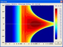
Hornresp Version 21.20 has just been released. Directivity polar maps can now be generated using the Tools > Directivity > Polar Map menu.
While Hornresp polar maps are not as accurate as those produced using Boundary Element Method techniques, they nevertheless give a reasonably useful insight into the directivity characteristics of horns and OS waveguides.
Note that moving the mouse pointer over the map area will display the SPL value for a given frequency and off-axis angle. In effect, the polar map shows on the one diagram all the information available from a family of directivity response curves generated at different off-axis angles.
Note also that polar maps for constant directivity devices (conical horns and OS waveguides) take longer to produce than those for other horn types because more calculations are involved.
As always, could you please let me know if you find any bugs in the new release, regardless of how minor they may seem to you. Many thanks.
Kind regards,
David
Hi Everyone,
Hornresp Version 21.20 has just been released. Directivity polar maps can now be generated using the Tools > Directivity > Polar Map menu.
While Hornresp polar maps are not as accurate as those produced using Boundary Element Method techniques, they nevertheless give a reasonably useful insight into the directivity characteristics of horns and OS waveguides.
Note that moving the mouse pointer over the map area will display the SPL value for a given frequency and off-axis angle. In effect, the polar map shows on the one diagram all the information available from a family of directivity response curves generated at different off-axis angles.
Note also that polar maps for constant directivity devices (conical horns and OS waveguides) take longer to produce than those for other horn types because more calculations are involved.
As always, could you please let me know if you find any bugs in the new release, regardless of how minor they may seem to you. Many thanks.
Kind regards,
David
Attachments
Re: Hornresp Version 21.20
Hi Everyone,
Further to my message above, I should have mentioned that a Hornresp polar map takes only minutes to produce, whereas a BEM plot generated to the same resolution takes many hours") .
.
Kind regards,
David
David McBean said:While Hornresp polar maps are not as accurate as those produced using Boundary Element Method techniques, they nevertheless give a reasonably useful insight into the directivity characteristics of horns and OS waveguides.
Hi Everyone,
Further to my message above, I should have mentioned that a Hornresp polar map takes only minutes to produce, whereas a BEM plot generated to the same resolution takes many hours
.Kind regards,
David
Re: Re: Hornresp Version 21.20
David,
That's a great step for Hornresp!
Another interesting feature to add to Hornresp should be the exportation of a calculated pulse response.
Thank you a lot for all!
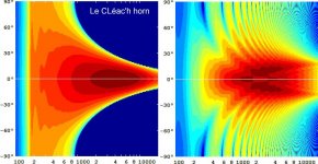
attached 2 polars: one for a FC = 160Hz T = 0.8 Le CLéac'h horn, the second (right) a waveguide of the same overall dimensions.
Best regards from Paris,
Jean-Michel Le Cléac'h
David,
That's a great step for Hornresp!
Another interesting feature to add to Hornresp should be the exportation of a calculated pulse response.
Thank you a lot for all!
attached 2 polars: one for a FC = 160Hz T = 0.8 Le CLéac'h horn, the second (right) a waveguide of the same overall dimensions.
Best regards from Paris,
Jean-Michel Le Cléac'h
David McBean said:
Hi Everyone,
Further to my message above, I should have mentioned that a Hornresp polar map takes only minutes to produce, whereas a BEM plot generated to the same resolution takes many hours
Kind regards,
David
Attachments
HELP!!
I consider myself to be fairly bright, but I'm beginning to questions this as I seem to be the only one who cannot make this work no matter how I try...
First, I've read through the help files repeatedly, as well as most of this thread, but I simply cannot get the Tapped horn wizard to appear; the button in the tools menu remains dimmed, and when I double click the "nd" field until it says TH, I receive the error message "Invalid TH Data"...and the "TH" Wizard button remains dimmed...
Also, I'm baffled by the "Parameter calculator"...the tutorial on this site states: "Just double-click on the tab and a calculator will appear that will calculate the mechanical parameters from the T/S-parameters (Fs, Qes, Qms. Vas)." When I do this, I get a box that asks "are you sure that (sd, bl etc.) are correct?" Of course I'm not sure! That's why I need the calculator! Am I misunderstanding what is meant by "tab"? I don't see what I usually think of as a tab in the "input parameters" window, so I assumed the boxes for the t/s values were being refered to...
Sorry if I got a little long winded with my first post to this forum, I just wanted to make my questions clear so that you would have the ammunition to answer them. Thank you for any help and God bless you, Mr. McBean, for providing a software package for free that does what many rather pricey packages do not offer...and do it very, very well, by all accounts!!
Michael
To get the tapped horn wizard appear you must have: Put Hornresp in tapped horn mode; Tools -- Driver Arrangement -- Tapped horn.
Either Vrc or Lrc left blank.
Have at least three complete segments (S1, S2, L12, S3, L23, S4, L34).
When these criteria are met you should have acces to the tapped horn wizard.
With "tab" a input parameter field is meant. Those are the fields that are highlited each time you press the "tab"-button.
Best regards Johan
Either Vrc or Lrc left blank.
Have at least three complete segments (S1, S2, L12, S3, L23, S4, L34).
When these criteria are met you should have acces to the tapped horn wizard.
Hornresp calculates the other T/S-parameters, you do not know, like the Fs, Vas, Qes, Qms and Qts. All the other parameters you're supposed to know (or calculate those when you double click the input field.Also, I'm baffled by the "Parameter calculator"...the tutorial on this site states: "Just double-click on the tab and a calculator will appear that will calculate the mechanical parameters from the T/S-parameters (Fs, Qes, Qms. Vas)." When I do this, I get a box that asks "are you sure that (sd, bl etc.) are correct?" Of course I'm not sure! That's why I need the calculator!
With "tab" a input parameter field is meant. Those are the fields that are highlited each time you press the "tab"-button.
Best regards Johan
Directivity (beaming) of diaphragm?
Hornresp don't seem to take this into account.
How does this affect the accuracy of plots with large drivers?
Would there be possible to get a directivity plot of a closed box (extremely short 'horn') out of hornresp? Using 1cm straight guide seems to be OK for lower frequencies (i think) but for HF I'm not sure where the model falls apart.
Or is the plot only meant to show you ripple and other stuff you want to be aware of when designing?
BTW the polar plot is fun to play with. It's so much easier to see and imagine directivity.
Strange peaks in phase and GD when using damping material.
When I use damping in a closed box I get strange peaks.
They appear regardless of damping density.
Also the SPL response at 100-800Hz is altered and is virtually the same regardless of density. It only changes with thickness.
This is with a 15" speaker in a 30L box btw.
Another thing.
I saw another program a while ago that took into account the depth if the cone. With internal resonances and other effects that comes with a real cone not being flat.
Is this a thought about feature for hornresp?
I could only imagine how infinitely more complex things would get.
Re: HELP!!
Hi Michael,
Further to Johan's comments:
If you move the mouse pointer over the "Invalid TH data" message, an explanatory note will appear in the status bar panel at the bottom of the window indicating the cause of the problem. The necessary prerequisites for a tapped horn are also detailed in Note 8 on page 17 of the Hornresp Help file.
Assuming that you have the Thiele-Small parameter values Sd, fs, Qes, Qms and Vas, and the values for Le and Re, then you have all the information that you need to calculate the equivalent electro-mechanical input values used in Hornresp.
Double click-on the Cms input box in edit mode and follow the instructions. Then do the same with the Mmd, Bl and Rms input boxes, in that order.
Hope this helps.
Kind regards,
David
Hi Michael,
Further to Johan's comments:
bigdaddyrox4574 said:When I double click the "Nd" field until it says TH, I receive the error message "Invalid TH Data"...and the "TH" Wizard button remains dimmed...
If you move the mouse pointer over the "Invalid TH data" message, an explanatory note will appear in the status bar panel at the bottom of the window indicating the cause of the problem. The necessary prerequisites for a tapped horn are also detailed in Note 8 on page 17 of the Hornresp Help file.
bigdaddyrox4574 said:I get a box that asks "are you sure that (sd, bl etc.) are correct?"
Assuming that you have the Thiele-Small parameter values Sd, fs, Qes, Qms and Vas, and the values for Le and Re, then you have all the information that you need to calculate the equivalent electro-mechanical input values used in Hornresp.
Double click-on the Cms input box in edit mode and follow the instructions. Then do the same with the Mmd, Bl and Rms input boxes, in that order.
Hope this helps.
Kind regards,
David
Re: Re: Re: Hornresp Version 21.20
Hi Jean-Michel,
I looked at the feasibility of doing this some time ago, but decided not to proceed because of the amount of work involved.
Thanks for posting the two polar plots. I know which one I prefer.
Kind regards,
David
Hi Jean-Michel,
Jmmlc said:Another interesting feature to add to Hornresp should be the exportation of a calculated pulse response.
I looked at the feasibility of doing this some time ago, but decided not to proceed because of the amount of work involved.
Jmmlc said:Attached 2 polars: one for a FC = 160Hz T = 0.8 Le CLéac'h horn, the second (right) a waveguide of the same overall dimensions.
Thanks for posting the two polar plots. I know which one I prefer
.Kind regards,
David
David_Web said:
Directivity (beaming) of diaphragm?
Hornresp don't seem to take this into account.
How does this affect the accuracy of plots with large drivers?
Would there be possible to get a directivity plot of a closed box (extremely short 'horn') out of hornresp? Using 1cm straight guide seems to be OK for lower frequencies (i think) but for HF I'm not sure where the model falls apart.
Or is the plot only meant to show you ripple and other stuff you want to be aware of when designing?
BTW the polar plot is fun to play with. It's so much easier to see and imagine directivity.
Strange peaks in phase and GD when using damping material.
When I use damping in a closed box I get strange peaks.
They appear regardless of damping density.
Also the SPL response at 100-800Hz is altered and is virtually the same regardless of density. It only changes with thickness.
This is with a 15" speaker in a 30L box btw.
Another thing.
I saw another program a while ago that took into account the depth if the cone. With internal resonances and other effects that comes with a real cone not being flat.
Is this a thought about feature for hornresp?
I could only imagine how infinitely more complex things would get.
Hi David_Web,
As indicated in Note 2 on page 15 of the Hornresp Help file, the driver diaphragm is modelled as a rigid plane circular piston. I have no plans to change this. It is virtually impossible to take cone angle and surface resonances into account unless finite element analysis techniques are used (assuming that the cone geometry, material structure and vibration characteristics can be accurately specified in the first place).
For a direct radiator in a closed box, set S1 and S2 = Sd and L12 (Exp) = 0.01. The directivity results will be similar to those for a rigid circular piston in an infinite baffle.
As you have discovered, damping is very dependent on the thickness (or more correctly, the volume) of the acoustical lining material.
Kind regards,
David
Isobarik mounting
Another quick question, if I haven't worn out my welcome yet; how would one adjust the driver parameters in Hornresp to account for an isobarik configuration? I know that normally, you reduce the vas by 1/2 and the re by 1/2 or double, depending on wiring, but Hornresp doesn't use vas and I'm not sure which of the parameters it does use would be affected by the change(...I'm also a little spoiled after using WinISD for years and having it do the work for me) .
P.S.; Thanks again to all who helped with Tapped Horn questions...I already have a project in the planning stages
Another quick question, if I haven't worn out my welcome yet; how would one adjust the driver parameters in Hornresp to account for an isobarik configuration? I know that normally, you reduce the vas by 1/2 and the re by 1/2 or double, depending on wiring, but Hornresp doesn't use vas and I'm not sure which of the parameters it does use would be affected by the change(...I'm also a little spoiled after using WinISD for years and having it do the work for me
) .P.S.; Thanks again to all who helped with Tapped Horn questions...I already have a project in the planning stages
There was some discussion of that in the live-sound thread.
If I recall, the consensus reached was that isobaric loading is really not a good idea in a horn cabinet, as there are generally better choices for drivers available.
http://www.diyaudio.com/forums/showthread.php?postid=1768990#post1768990
If I recall, the consensus reached was that isobaric loading is really not a good idea in a horn cabinet, as there are generally better choices for drivers available.
http://www.diyaudio.com/forums/showthread.php?postid=1768990#post1768990
One more question...
Interesting... I had a bad feeling that might be the case. In retrospect, I think that's about why I never tried isobarik with a vented, bandpass or other non-horn enclosure...the predicted results never seemed worth it when you considered the loss of efficiency etc..
Another question about tapped horns: It seems that early on, when I first began researching these things, I read that not only are the peaks and valleys that you see in the sim smoothed out in the actual, measured response of the final product, but the efficiency is reduced. Now, even if it is reduced by 6 db in the project I'm planning, the results will be spectacular! It seems to be predicting efficiency in the 110 to 113 db range in the passpand, and this is for a 6.5 inch driver in 2.5 ft^3 enclosure! Indeed, even the lowest dip in the plot is around 98 db; that's about 10 db better then the drivers reference efficiency. All of that being said, I would still like to know what I can expect in the real world.
Thanks again for all of your help;
Michael Stigall
Measurements I posted in the Collaborative Thread
There are a bunch of other people that have built these and posted their measured results. I was low, but within a few dB, I am sure that some was my measurement technique and the location I used. Most importantly - the response was smoother than predicted by the model.
There are a bunch of other people that have built these and posted their measured results. I was low, but within a few dB, I am sure that some was my measurement technique and the location I used. Most importantly - the response was smoother than predicted by the model.
Re: Isobarik mounting
Hi Michael,
Don't forget that Vas values can be entered into Hornresp using the Calculate Parameter tool.
Kind regards,
David
bigdaddyrox4574 said:But Hornresp doesn't use vas.
Hi Michael,
Don't forget that Vas values can be entered into Hornresp using the Calculate Parameter tool
.Kind regards,
David
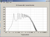
Hmmm. Your plot looks very different from what I get. I thought I was on the right track because mine looks a lot like the one at the beginning of the Tapped horn thread, but now I wonder... Can you guys look at my predicted plot and tell me if it looks like it should?
Attachments
- Home
- Loudspeakers
- Subwoofers
- Hornresp