Adding heavily concentrated stuffing is not my idea of a good implementation, and generally one stub is more appropriate, but yes, for simulation purposes holes down the flute is a correct analogy. Each hole length and diameter is treated like a port of a base reflex. Generally the totall volume will probably not be more than a bass reflex port.
That TL seems to have each stub sealed. Seems like ti does not allow flute type ports or long slotted port?
Yes, this software does allow for flute type open ended ports at any location on the line and long slotted ports and just about anything else you could want.
It allows any number of elements (segments) in series on either side of the driver, and each series element can have any number of elements branched off of it, each of which can be any shape and size you want, and each of which can have an open or closed end. This software will sim almost any configuration you can dream up with very few exceptions.
The software is fairly new and the tapped horn feature isn't working properly yet, but several people have compared simulations of the same design in other programs (Hornresp and MJK's worksheets) and the TL.app results are very good. Here's a comparison I did against Hornresp to show that TL.app does what it's supposed to. (Hornresp sims power response and TL.app sims on axis response and there may be other small internal differences as well, so there are naturally some small differences in the simulation results.) http://www.diyaudio.com/forums/soft...n-line-modelling-software-44.html#post3397872
TL.app is available here - Leonard Audio | Audio Engineering Resources
User guide is here so you can see it's features - http://leonardaudio.co.uk/wp-content/uploads/2013/12/TL-UserGuide.pdf
The only reason I posted the Hegeman sim is because I had it on hand readily available and it shows that the software is capable of simulating branches located at any area in the line. I didn't mean to suggest that the Hegeman approach was exactly what you wanted to do.
Last edited:
Thanks for clearing that up.
Hi Oliver,
One of the conditions that causes the mathematics of the lossy model to break down is having a parabolic profile with a very low positive or negative flare rate. It turns out that this is the case for your example - if L12 and L23 are changed from Par to Con, the problem goes away
") .
.It got me thinking...
The next release (tentatively planned for 1 January 2014) will check if a lossy parabolic profile has a very low flare rate, and if so, automatically substitute a lossy conical flare instead. Because the flare rate is so low, it will make no observable difference to the results - the user will not even be aware that the calculations are being done any differently. I have already tested the proposed enhancement, and it works well!
Thanks for raising this issue - it prompted me to develop and implement the above change. It won't fix everything, but should certainly help for enclosures with very low parabolic taper rates.
Kind regards,
David
Yes, this software does allow for flute type open ended ports at any location on the line and long slotted ports and just about anything else you could want.
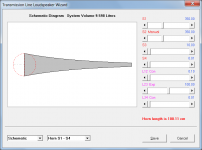
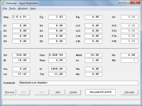
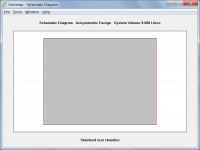
Look ma, I made a flute. (But all the holes have different length and cross sectional areas, and some of the holes are open ended and some are closed ended.)
An externally hosted image should be here but it was not working when we last tested it.
It took about 49 seconds to create this (the software is very easy to use).
And I can move the driver and/or each of the ports to any location on the line by dragging it by it's handle in the schematic drawing. The cross sectional area and length of each segment can also be edited by manipulating the schematic or inputting info in the text boxes on the right. I could have included elements on the front of the driver too (front loaded) but then it wouldn't look like a flute at all.
Anyway, PM me if you want more info, I don't want to put too much OT in the Hornresp thread.
Last edited:
However the article by Claus Futtrup is one of the most lucid examples of how it really works.
Hi Mark,
Unfortunately we keep coming back to the fundamental problem of having to determine the voice coil temperature. Claus Futtrup indicates that this is one of the "minimum" parameters required when calculating power compression. He calls it Tmax, and seems to assume a value of 270 degrees Celsius.
Kind regards,
David
I would love to see the capability for controlled leakage pattern.
Hi soongsc,
Sorry, its not going to happen
.Maybe you could use the Transmission Line software, as suggested by 'just a guy'?
Kind regards,
David
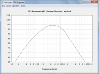
TL.app sims on axis response
Hi just a guy,
Do you know how TL.app calculates on-axis pressure response?
It seems to me that for a transmission line type loudspeaker at least, it would be necessary to know the directivity characteristics of each output, and how they combine, to be able to accurately predict the pressure response at higher frequencies. Are the physical locations of the two outputs and their relationship to each other, specified as inputs, perhaps?
Kind regards,
David
Hi just a guy,
Do you know how TL.app calculates on-axis pressure response?
You are asking the wrong guy. I asked him recently exactly what the program simulates and this was his answer.
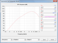
Also, the response is the on-axis sound pressure level at 1m
http://www.diyaudio.com/forums/soft...n-line-modelling-software-52.html#post3740399
It seems to me that for a transmission line type loudspeaker at least, it would be necessary to know the directivity characteristics of each output, and how they combine, to be able to accurately predict the pressure response at higher frequencies. Are the physical locations of the two outputs and their relationship to each other, specified as inputs, perhaps?
Kind regards,
David
Are you referring to something like Hornresp's combined response path length difference? If so, the program "knows" where driver is and where all the holes are, but I have no idea how much it takes into consideration when doing the calculations. I would assume that the program does not calculate the schematic literally, since the user could choose to fold the enclosure and/or the ports, and put the ports internal or external to the enclosure, and put the ports on any of the four sides of the enclosure as long as port location vs line length is correct.
All the "enclosure" inputs for TL.app can be seen in the right hand margin of the "Enclosure" window (previously called the "Geometry Display" window) screenshots I've shown. There's no more inputs than that, the program auto-updates immediately and there's no pop up text boxes or anything like that, what you see is all there is. (There are a couple of ways to manipulate the schematic drawing itself that don't have text box inputs, but nothing like what I think you are asking about.)
Anyway, Hornresp's Loudspeaker Wizard and MJK's simple model (Part 1 of each worksheet) don't have a combined response path length difference either, and MJK's software also shows on axis response. I assume this is how TL.app works too, with no consideration of combined response path length differences.
I'll ask him if you like, I just need to know exactly what you need to know first. Or you can ask him. He would probably be happy to chat with you about this and other things, the tapped horn feature needs a bit of work.
All I really know is that everyone who has compared his program to yours and MJK's has had favorable things to say, including myself (with the exception of the tapped horn feature). To be clear, I've only done one detailed comparison though. The differences I see are definitely within reason and small differences are to be expected when comparing different programs by different authors that may be calculating things differently or showing different things (like on axis vs power response).
Last edited:
I'll ask him if you like,
Hi just a guy,
Not to worry, thanks - it was just a general interest question.
I guess the software must be making some simple assumptions regarding directivity, given the seemingly limited information it has to work with.
Kind regards,
David
Anyway, Hornresp's Loudspeaker Wizard and MJK's simple model (Part 1 of each worksheet) don't have a combined response path length difference either,
Hi just a guy,
Just to clarify - the Hornresp Loudspeaker Wizard does have a combined response path length difference slider.
Kind regards,
David
Attachments
Thanks, I should give it a try.Look ma, I made a flute. (But all the holes have different length and cross sectional areas, and some of the holes are open ended and some are closed ended.)
An externally hosted image should be here but it was not working when we last tested it.
It took about 49 seconds to create this (the software is very easy to use).
And I can move the driver and/or each of the ports to any location on the line by dragging it by it's handle in the schematic drawing. The cross sectional area and length of each segment can also be edited by manipulating the schematic or inputting info in the text boxes on the right. I could have included elements on the front of the driver too (front loaded) but then it wouldn't look like a flute at all.
Anyway, PM me if you want more info, I don't want to put too much OT in the Hornresp thread.
Hi soongsc,
Sorry, its not going to happen
Maybe you could use the Transmission Line software, as suggested by 'just a guy'?
Kind regards,
David
Hi danid,
No problem. I am used to putting the pieces together myself.
Hi Mark,
Unfortunately we keep coming back to the fundamental problem of having to determine the voice coil temperature. Claus Futtrup indicates that this is one of the "minimum" parameters required when calculating power compression. He calls it Tmax, and seems to assume a value of 270 degrees Celsius.
Kind regards,
David
I know this is a stupid answer.
But...
Doesn't the temperature begin at driver ambient temperature.
Doesn't the temperature begin at driver ambient temperature.
Hi Mark,
Yes it does. Claus Futtrup assumes that the nominal value of Re is measured at 20 deg C. Unfortunately this doesn't help in determining the final voice coil temperature Tmax.
Kind regards,
David
The Nautilus is a sealed tl. As far as I know you can't do that with Hornresp. You could make a tiny terminus to make it a leaky sealed tl but I wouldn't do that. I'd simulate it with MJK's software or TL.app. I don't bother with Akabak if I need stuffing but if you've got stuffing figured out in Akabak you could use that program too.
EDIT - the Nautilus is also end loaded and the Hornresp stuffing feature won't work with Nd, only Od or TH.
Aside from that, Hornresp's stuffing feature seems to be working fine for me regardless of whether the tl taper is positive, negative, straight or a more complex taper geometry.
EDIT - the Nautilus is also end loaded and the Hornresp stuffing feature won't work with Nd, only Od or TH.
Aside from that, Hornresp's stuffing feature seems to be working fine for me regardless of whether the tl taper is positive, negative, straight or a more complex taper geometry.
Last edited:
How would I go about simulating a tapered absorbing tube (e.g.: B&W Nautilus) in Hornresp?
Hi Oliver,
I wouldn't bother
.Call me a cynic, but as far as I can see the "tapered absorbing tube" is simply a marketing gimmick. In the case of the Nautilus it might look neat, and help to justify the staggeringly high price, but if it makes the speaker sound any better then it is most likely due to the solid construction, rather than to anything else.
In effect, what we have is a traditional absorbent-filled "acoustic suspension" loudspeaker - just with a more fancy enclosure.
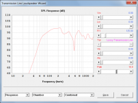
Out of interest, I tried simulating the enclosure firstly as a Nautilus-type tapered exponential lossy "transmission line", and then as a simple filled sealed box. As expected, the two SPL response results are much the same.
Hope I haven't offended too many Nautilus speaker owners
.Kind regards,
David
Attachments
You got the wrong tuning.
Hi soongsc,
Not sure that I understand. Could you please clarify?
Kind regards,
David
- Home
- Loudspeakers
- Subwoofers
- Hornresp