I would be grateful if you advise more books and articles on the subject of mathematical calculation frequency response.
Hi Ural sound,
The following three textbooks contain detailed descriptions of the classic lumped-element model normally used to calculate loudspeaker frequency response.
"Acoustical Engineering" by Harry F. Olson
"Acoustics" by Leo L. Beranek
"Acoustics - Sound Fields and Transducers" by Leo L. Beranek & Tim J. Mellow
The third book is the most recently published - it would be a good place to start.
Kind regards,
David
hornresp on linux / MAC ")
Good News for all you Linux/MAC Users:
I´ve managed to put hornresp in a virtual machine running on VMWARE Player using Reactos instead of Windows as a basis... Reactos is an open source OS, so its free.
ReactOS Project
VMWARE Player is the free version of the virtualization Technology by VMWare, it´s available for Linux and Windows.
https://my.vmware.com/web/vmware/free#desktop_end_user_computing/vmware_player/6_0
Mac Users can use Fusion (free Trial available)
https://www.vmware.com/products/fusion/
I´ll whip something together for you guys to use it, weekend is coming and jobs are waiting, so please be patient Look ahead to this:

It works with a few little drawbacks (screen refresh sometimes a littel off, nothing serious).
(This "trick" generally works with VirtualPC, too, so we can manage to get a complete free solution even for MAC users, but my machine is having trouble with virtualPC for the moment, so I am stuck to VmWAre for the moment..)
Of course the PC-Geeks among us can simply go ahead themselfes, heres the fast version of HOW TO RUN HORNRESP on LINUX or MAC
- Install VMWARE Player / Fusion
- Download VMWARE Image of Reactos
- Run Reactos Virtual Machine
- Download Firefox within Reactos
- download hornresp
- GO
Same with virtual PC
Good News for all you Linux/MAC Users:
I´ve managed to put hornresp in a virtual machine running on VMWARE Player using Reactos instead of Windows as a basis... Reactos is an open source OS, so its free.
ReactOS Project
VMWARE Player is the free version of the virtualization Technology by VMWare, it´s available for Linux and Windows.
https://my.vmware.com/web/vmware/free#desktop_end_user_computing/vmware_player/6_0
Mac Users can use Fusion (free Trial available)
https://www.vmware.com/products/fusion/
I´ll whip something together for you guys to use it, weekend is coming and jobs are waiting, so please be patient
Look ahead to this:
It works with a few little drawbacks (screen refresh sometimes a littel off, nothing serious).
(This "trick" generally works with VirtualPC, too, so we can manage to get a complete free solution even for MAC users, but my machine is having trouble with virtualPC for the moment, so I am stuck to VmWAre for the moment..)
Of course the PC-Geeks among us can simply go ahead themselfes, heres the fast version of HOW TO RUN HORNRESP on LINUX or MAC
- Install VMWARE Player / Fusion
- Download VMWARE Image of Reactos
- Run Reactos Virtual Machine
- Download Firefox within Reactos
- download hornresp
- GO
Same with virtual PC
Yes, for the forces due to accelerating the mass................You would have to agree though, using Mmd would definitely provide the worst case scenario..........
I admit I am not familiar with how driver compression ratios are defined, but in terms of volume compression, it would take a real strong motor to compress 20:1, what driver has that capability?
If we know a compression ratio, based in the area under pressure you can calculate a total pressure, but the real stress on the cone is bending caused by pressure distribution. If this is not calculated, I am wondering how useful the data can be. However, since it is already implemented...
Here is just a small list of things Hornresp doesn't do. It doesn't calculate in more than one dimension (the length dimension), it doesn't calculate boundary layer skin friction, the operating temperature of the driver, the weather and altitude, laminar vs turbulent airflow, the compressability of air, it can't accurately model effects of Le and it assumes the boundaries are infinitely rigid. And that's a small list, I could go on and on and on.
These are not minor issues, you really have to know what you are doing if you have any hope of producing a physical product whose measurements at high power match your simulation.
I could say "If all of this is not calculated, I am wondering how useful the data can be." But instead, I am happy that I have any data at all. I try to understand the limitations of the software and make educated guesses about the stuff it can't predict.
People have been talking about compression ratio and cone failure since decades before I was born. Until a couple of days ago the general public (non Akabak users) had no way to quantify these questions and concerns. Now there is a way to get a little bit of data. It's not a complete data set but it's a lot better than nothing.
I am not sure what Akaback actually does, but I am thinking if you data cannot be used in practice, why spend time coding it? Rupture of a cone is generally due to stress concentration seldom does pressure get hight enough to exceed the diaphragm material capability over the surface.
Now, if were are trying to look at pressure variation to possibly lower distortion, then that is a different story.
Now, if were are trying to look at pressure variation to possibly lower distortion, then that is a different story.
I am not sure what Akaback actually does,
Akabak has a Driver (diaph) Driver graph, which is the same thing as Hornresp's new Total Pressure graph.
... but I am thinking if you data cannot be used in practice, why spend time coding it? Rupture of a cone is generally due to stress concentration seldom does pressure get hight enough to exceed the diaphragm material capability over the surface.
Pressure doesn't usually get high enough to cause damage because we have rules of thumb to prevent it. 3:1 compression ratio is generally considered safe, venture beyond that at your own risk.
In this case, I can look at the pressure caused by a 3:1 ratio and then increase that ratio. Nothing else changes, the mass/acceleration factor does not increase, the cone material, cone thickness, cone composition, cone geometry and dustcap location do not change, NOTHING but the compression ratio changes. The geometry of the horn itself doesn't change much either, so pressure distribution does not change. So I can look at the Total Pressure and easily track how much extra pressure the added compression adds.
Even if the Total Pressure graph was completely useless for this purpose, I can still use it for reactance annulling purposes.
I'm not sure what your end game is, are you arguing that the Total Pressure graph should be removed from Hornresp? If so I will fight to keep it. If not we can agree to disagree and move on.
Good News for all you Linux/MAC Users:
Brilliant - thanks Sabbelbacke!
Kind regards,
David
No problem, I needed to do it anyway since I didn't know the answer either.
Hi just a guy,
If it is not too much trouble, would it be possible for you to do another comparison using the same Polyfill stuffing material as before, but in system having different cross-sectional areas and lengths? It would be very interesting to see if the density versus flow resistivity relationships remain constant.
That is:
0.25 lb/ft3 ~ 125 mks rayls/m
0.50 lb/ft3 ~ 400 mks rayls/m
0.75 lb/ft3 ~ 600 mks rayls/m
Thanks in anticipation.
Kind regards,
David
Last edited:
It makes no difference to me if it's in or out. But if you all like it, have fun. I just think if that is there, it's worth going the extra mile to make it more realistic by getting BL and Km vs excursion in there....
I'm not sure what your end game is, are you arguing that the Total Pressure graph should be removed from Hornresp? If so I will fight to keep it. If not we can agree to disagree and move on.
Hi just a guy,
If it is not too much trouble, would it be possible for you to do another comparison using the same Polyfill stuffing material as before, but in system having different cross-sectional areas and lengths? It would be very interesting to see if the density versus flow resistivity relationships remain constant.
That is:
0.25 lb/ft3 ~ 125 mks rayls/m
0.50 lb/ft3 ~ 400 mks rayls/m
0.75 lb/ft3 ~ 600 mks rayls/m
Thanks in anticipation.
Kind regards,
David
I'm happy to help in any way I can. Just give me a input screenshot or Hornresp import file of what you would like to see simulated and I'll run the numbers through both programs and do another comparison.
Well... probably not many people have been calculating pressure at all yet, and especially not in kg so there's really no point of reference to find out if that's a lot or not. And as soongsc has been pointing out, when it comes to predicting the point of pressure induced cone failure there's more to it than a Hornresp graph can show. Personally, I've mainly been using the pressure graphs as a relative comparison between designs, I've not yet done any kind of comprehensive study on predicted failure points. You have to know a LOT about the driver if you want to do that.
You'd probably have better luck posting up the design itself and asking for opinions on whether it's too much for the driver to handle, at least until more people are more familiar with the new Total Pressure graph. We've always had pretty strong opinions on this even before anyone was using pressure graph info.
You'd probably have better luck posting up the design itself and asking for opinions on whether it's too much for the driver to handle, at least until more people are more familiar with the new Total Pressure graph. We've always had pretty strong opinions on this even before anyone was using pressure graph info.
Last edited:
I'm happy to help in any way I can. Just give me a input screenshot or Hornresp import file of what you would like to see simulated and I'll run the numbers through both programs and do another comparison.
Hi just a guy,
Excellent - many thanks!
Data attached as requested.
Kind regards,
David
Attachments
is it posible to implement to change s2 to s3 position in th modus(simular to the th>th1 function)?
Hi epa,
Not sure that I understand - do you mean "th modus" or "od modus"?
A 3 segment TH tapped horn has driver entry points at S2 and S3.
A 4 segment TH tapped horn has driver entry points at S2 and S4.
A 4 segment TH1 tapped horn has driver entry points at S2 and S3.
An offset driver (OD) horn has the driver entry point at S2.
Are you asking for the offset driver entry point to be moved from S2 to S3, perhaps?
Kind regards,
David
i meanth a th.
i want flexabilety behind the first entry point.
to use youre example:
A 4 segment TH2 tapped horn has driver entry points at S3 and S4
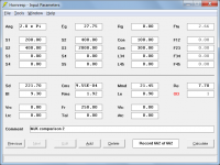
@David_Web
A couple of questions.
This is simulated as a tapped horn?
And you have created the momentary mass at this power level by what mathematical method?
Pressure multiplied by Sd? So 855 x 7.18 = 6140
If that is the case you are approximately 7 grams per cm^2 not to bad.
If you are doing a force calculation of the voice coil junction to the woofer cone it is a bit more interesting.
The voice coil former is approximately 100 mm so we have a circumference :
Pi x D 3.14 x 10 = 31.4 cm Glue joint area is probably 0.4cm so 31.4 x 0.4 = 12.56 cm^2
Take your momentary mass number of 6140 grams and divide it by the glue joint area and it is a bit more stressful
6140 / 12.56 = 488.85 grams per square centimeter.
Even this line of reasoning has it's flaws. We are ignoring the glue joint at the spider as a source of spreading losses in the point of attachment and the losses induced as heat in the flexure at the surround terminations both at the cone edge and the basket edge. Never mind the flexure of the surround itself. There are nice sophisticated FEA programs that take a stab at this. And they are simply informed guesses that we use to try and understand what we can see and measure.
Crumple forces, or cone flexure and failure is more critical than momentary force numbers.
The peaks in a musical signal are almost always less than a second or two, and have a rice and fall along with a crest. So the stresses are not as severe as it might look.
Turns out I managed to get my initial kg calculations right.
61,4kg for a 15" dumping 1410W into it.
Would this be survivable for a good 15"?
In this case B&C 15TBW100.
A couple of questions.
This is simulated as a tapped horn?
And you have created the momentary mass at this power level by what mathematical method?
Pressure multiplied by Sd? So 855 x 7.18 = 6140
If that is the case you are approximately 7 grams per cm^2 not to bad.
If you are doing a force calculation of the voice coil junction to the woofer cone it is a bit more interesting.
The voice coil former is approximately 100 mm so we have a circumference :
Pi x D 3.14 x 10 = 31.4 cm Glue joint area is probably 0.4cm so 31.4 x 0.4 = 12.56 cm^2
Take your momentary mass number of 6140 grams and divide it by the glue joint area and it is a bit more stressful
6140 / 12.56 = 488.85 grams per square centimeter.
Even this line of reasoning has it's flaws. We are ignoring the glue joint at the spider as a source of spreading losses in the point of attachment and the losses induced as heat in the flexure at the surround terminations both at the cone edge and the basket edge. Never mind the flexure of the surround itself. There are nice sophisticated FEA programs that take a stab at this. And they are simply informed guesses that we use to try and understand what we can see and measure.
Crumple forces, or cone flexure and failure is more critical than momentary force numbers.
The peaks in a musical signal are almost always less than a second or two, and have a rice and fall along with a crest. So the stresses are not as severe as it might look.
Last edited:
Hi just a guy,
Excellent - many thanks!
Data attached as requested.
Kind regards,
David
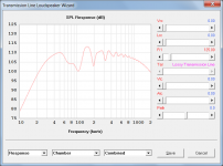
I didn't even look at the attached text file, I just used the input screenshot.
I had to use MJK's TL_Sections worksheet for this one since it isn't a straight line, it's pinched at S2. (I used the TL_Open_End worksheet on the previous comparison).
As always, check my inputs, if those are not correct nothing else will be.
I compared exactly the same thing as last time.
0 lb/ft - 0 Fr1
.25 lb/ft - 125 Fr1
.5 lb/ft - 400 Fr1
.75 lb/ft - 600 Fr1
Same as last time, I think 125 is a bit too low to correspond with .25 lb/ft but the other two seem to be in the right ballpark. Definitely in the right neighborhood at least.
And remember that MJK's software assumes polyfil stuffing.
Let me know if you need anything else.
An externally hosted image should be here but it was not working when we last tested it.
Last edited:
- Home
- Loudspeakers
- Subwoofers
- Hornresp