iand said:Driver power rating is done on an "applied rms voltage into nominal impedance" basis.
Hi Ian,
Is there a reference source I could examine, regarding the above statement? Also, is the value of Re normally used as the nominal impedance? It would be a relatively simple matter to modify Hornresp accordingly, if what you say holds true generally.
As you can see, I am no expert when it comes to Pmax matters
") .
.Wouldn't setting Eg to an appropriate value (eg 100V for an 8 ohm driver rated at 1250W) and calculating the standard SPL response with Rg = 0, already give the "power-limited" result you are looking for?
Thanks,
David
Hi,
if you are looking for Max SPL vs frequency then McBean's method is correct.
If you are looking for what SPL is available using a specific Power amplifier then the alternative would be OK, provided that the Lower SPL limited by Xmax is shown.
This last can be got by setting the test voltage in the Input Parameters and then adding in the LF SPL correction off the max SPL that is Xmax limited. This could be an extra option , BUT NOT to replace McBean's current method.
iand said:The first is that driver power rating is done on an "applied rms voltage into nominal impedance" basis, so an 8 ohm driver rated at 1250W rms will survive a 100V rms bandlimited pink noise signal. So the number that is put into Hornresp for thermal power handling is based on this, not 1250W thermal dissipation in the voice coil.
What Hornresp does in the Max SPL tool is in effect to feed the driver with a Pmax (in the example case 1250)W sinewave signal, swept 20Hz-20kHz. If the cone displacement is greater than Xmax, input power is recalculated to get displacent equal to Xmax.
When feeding the driver with a 100V rms pink noise signal, the power at each frequency is nowhere near 1250W. I don't think many 1250W rated drivers can take 1250W continous sinewave power for more than a fraction of a second without damage.
So the Max SPL calculated by Hornresp is unrealistic viewed this way. But your suggested method of specifying Vrms into a nominal impedance (which could be specified in the same dialog box) has just the same problem: the calculations uses the power at one frequency, while the driver rating is the integrated power over an (unspecified) frequency band.
When the amp will clip is not really relevant for Hornresp. When you desing a speaker, it is IMHO more interesting what the speaker is capable of by itself, than what the amp-speaker can do, as the amp can easily be changed. Besides, amps have protection circuitry that will limit maximum current, some of them will trip at low power when the load is reactive.
Another point is that Hornresp does not model driver nonlinearity, so Max SPL calculations are only indications of system performance. I think that if a more elaborate Max SPL simulation should be included, it must also include driver nonlinearity. If not, one method is not much more accurate than another. And including driver nonlinearity requires lots of data that users normally don't have (BL and Cms vs x, termal behavior, etc).
If you have any references to simulation of maximum SPL given only Xmax and Pmax, both David and I would be interested.
But given the current limitations, I think the Hornresp implementation is as good as it gets.
Best regards,
Bjørn
Ian has a point an is of course correct that specs fo drivers and amps are rated the way he describes. The method to display max power in hornresp has one advantage IMHO:
The power ratings of a driver in a spec sheet are always derived from the driver built in a standard-box (most of the times, it´s a closed enclosure or a given reflex-type. Sometimes even open baffle)... Every other enclosure than the stated one in the specs puts the speaker in a different environment, where it behaves totaly different. Seeing where the speaker reaches thermal or mechanical limits gives me a better view of where the speaker is stressed more in a given hornresp-sim-design and lets me compare better between other sims.
Of course, this never gives you a 100% real-life performance and max-SPL result. Deriving max SPL using the spec-sheet ratings wouldn´t eather. Many reasons for that:
As Ian described, speakers are rated with a given full-range signal (White Noise, pink noise, bursts, sweeps, etc... depending on the measuerement method. Some are more practiacal than others. Review the AES papers for this). There simply is no information on how the speaker behaves if some frequencies are left out (pre-filtering via High-pass) oder what happens when the speaker has high accoustical loads (= e.g. in a horn where cone movement is lowered but electrical stress is still availabe. Heat dissipation changes rapidly from cooling through convection to radiation), or simply has a different alligning of the tuning in a ported reflex box (this get´s more complicated in a multi-ported enclosure).
So deriving a real-world max-spl from the specs is almost impossible. Things like power compression are left out, too, but are not the issue here anways.
If hornresp would show max SPL like many other sims, I´d have less information on how the relation of electrical and mechanical stress on the cone at given frequency is.
Like described before by Andrew, one can simply input the max-voltage in the input tab and have a look at the excursion tap on how the design would be limited mechanicaly.
There are many things, hornresp and many other sims don´t take into account when calculating max-SPL... The speaker surrounding can be progressive or lineaer, the stiffness of it changes with excursion, BL changes differently depending on the motor-design (lookup Klippel for a more detailed look on this parameter), different magnet materials behave differently when it comes to cooling (heat discharge to atmosphere by radiation) and different vc-materials heat up differntly when driven with high power resulting in the increase of Re an hence changin the Q-factors, lowering SPL etc......
IMHO, the purpose of the max feature is a guideline, not more... One has to meassure the actual max SPL to really find out whats happenig at high powers. One would be surprised how much sim and reality differ on this account. As Tom Danley pointed out a few days ago, even "the big ones" with i high reputation often don´t bother to really measure, they just interpolate....
So it´s fine the way it is for me. Adding a second curve using the "standard way" of taking the max possible voltage given from the spec sheet and subtracting the limited areas where xmax is reached would be a good compromise and be helfpul to compare results to other sims (like AjHorn e.g.):
One thing that would come in handy for me:
@david
could the max spl graph be duo-chrome? The electrical limited parts could be, lets say red, the ones where max-excursion is reached... black? This way it would be quicker to see which limit is reached at which freqency.
Not really important, but nice to have would be a graph of the other calculated results like efficiency in the max SPL graph.
The power ratings of a driver in a spec sheet are always derived from the driver built in a standard-box (most of the times, it´s a closed enclosure or a given reflex-type. Sometimes even open baffle)... Every other enclosure than the stated one in the specs puts the speaker in a different environment, where it behaves totaly different. Seeing where the speaker reaches thermal or mechanical limits gives me a better view of where the speaker is stressed more in a given hornresp-sim-design and lets me compare better between other sims.
Of course, this never gives you a 100% real-life performance and max-SPL result. Deriving max SPL using the spec-sheet ratings wouldn´t eather. Many reasons for that:
As Ian described, speakers are rated with a given full-range signal (White Noise, pink noise, bursts, sweeps, etc... depending on the measuerement method. Some are more practiacal than others. Review the AES papers for this). There simply is no information on how the speaker behaves if some frequencies are left out (pre-filtering via High-pass) oder what happens when the speaker has high accoustical loads (= e.g. in a horn where cone movement is lowered but electrical stress is still availabe. Heat dissipation changes rapidly from cooling through convection to radiation), or simply has a different alligning of the tuning in a ported reflex box (this get´s more complicated in a multi-ported enclosure).
So deriving a real-world max-spl from the specs is almost impossible. Things like power compression are left out, too, but are not the issue here anways.
If hornresp would show max SPL like many other sims, I´d have less information on how the relation of electrical and mechanical stress on the cone at given frequency is.
Like described before by Andrew, one can simply input the max-voltage in the input tab and have a look at the excursion tap on how the design would be limited mechanicaly.
There are many things, hornresp and many other sims don´t take into account when calculating max-SPL... The speaker surrounding can be progressive or lineaer, the stiffness of it changes with excursion, BL changes differently depending on the motor-design (lookup Klippel for a more detailed look on this parameter), different magnet materials behave differently when it comes to cooling (heat discharge to atmosphere by radiation) and different vc-materials heat up differntly when driven with high power resulting in the increase of Re an hence changin the Q-factors, lowering SPL etc......
IMHO, the purpose of the max feature is a guideline, not more... One has to meassure the actual max SPL to really find out whats happenig at high powers. One would be surprised how much sim and reality differ on this account. As Tom Danley pointed out a few days ago, even "the big ones" with i high reputation often don´t bother to really measure, they just interpolate....
So it´s fine the way it is for me. Adding a second curve using the "standard way" of taking the max possible voltage given from the spec sheet and subtracting the limited areas where xmax is reached would be a good compromise and be helfpul to compare results to other sims (like AjHorn e.g.):
An externally hosted image should be here but it was not working when we last tested it.
One thing that would come in handy for me:
@david
could the max spl graph be duo-chrome? The electrical limited parts could be, lets say red, the ones where max-excursion is reached... black? This way it would be quicker to see which limit is reached at which freqency.
Not really important, but nice to have would be a graph of the other calculated results like efficiency in the max SPL graph.
Sabbelbacke is agreeing with what I said -- in practice the maximum SPL is limited either by Xmax or the amplifier/speaker power rating, so it makes sense to be able to see this. If you just put the maximum voltage in as Eg then you can't see (on the SPL curve) where you hit the Xmax limit or how badly this restricts output.
Predicting a maximum output of 145dB at an impedance maximum is unusable in practice since no amplifier works like this (except maybe Bob Carver's "tracking downconverter" as used in the Sunfire subs).
It's true that if you change the enclosure then you change the power handling at each frequency, however it's unlikely for most enclosures (except full-size very efficient horns) that the average impedance over the band is changed so much, though cone travel may be.
So from the driver power handling point of view the best guess for maximum SPL is to use the manufacturers power rating (for continuous output) or a factor above this (3dB? 6db?) for peak output, this then also defines the size of the amplifier needed to reach this SPL.
In answer to David's question, drivers are rated as power into the nominal impedance, in other words rms applied voltage -- an 8 ohm nominal driver (Re typically around 6 ohms) which is rated at 1250W is actually tested with 100Vrms applied as bandlimited noise across the operating bandwidth, regardless of what the actual impedance is at any frequency.
For example, this is why the TH-115 (like many other speakers) can be rated as handling 2000W on peaks (1000W continuous) when the Xmax limit at the worst frequency is much smaller than this (almost 6dB lower), because only a small fraction of the power is at this frequency -- if you wanted to use it in (for example) a noise cancellation application where all the power could be in a single-frequency sinewave then the rating would be much lower.
Ian
Maximum SPL
Hi Everyone,
Thanks for the feedback on Pmax. After considering all of your comments, I have decided to leave the Hornresp Maximum SPL tool as it is. If loudspeaker driver manufacturers quoted a value for Vmax rather than Pmax, then perhaps I would think differently.
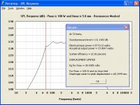
Sabbelbacke - The frequency at which the response changes from displacement-limited to power-limited is usually signalled by a slight discontinuity. For example, with the default record this occurs just above 72 hertz (see attached).
Thanks again for all of your contributions.
Kind regards,
David
Hi Everyone,
Thanks for the feedback on Pmax. After considering all of your comments, I have decided to leave the Hornresp Maximum SPL tool as it is. If loudspeaker driver manufacturers quoted a value for Vmax rather than Pmax, then perhaps I would think differently
.Sabbelbacke - The frequency at which the response changes from displacement-limited to power-limited is usually signalled by a slight discontinuity. For example, with the default record this occurs just above 72 hertz (see attached).
Thanks again for all of your contributions.
Kind regards,
David
Attachments
Hy David,
thanx for your reply and once again thanx for your support!!!
Of course, somtimes the point where xmax is reached often is seen quite good. I had more things like this in mind:
The first dip (from the left) is replacement related, the second one power limited. But his really is a very insignificant, it would be "nice to have" but just doing xmax once again with a higher power rating gives me an instant overview which is a good workaround.
Typing this, I recall that I totally forgot about the pictures from johans tutorial ...
thanx for your reply and once again thanx for your support!!!
Of course, somtimes the point where xmax is reached often is seen quite good. I had more things like this in mind:
An externally hosted image should be here but it was not working when we last tested it.
The first dip (from the left) is replacement related, the second one power limited. But his really is a very insignificant, it would be "nice to have" but just doing xmax once again with a higher power rating gives me an instant overview which is a good workaround.
Typing this, I recall that I totally forgot about the pictures from johans tutorial ...
Sabbelbacke said:Doing xmax once again with a higher power rating gives me an instant overview which is a good workaround.
Hi Sabbelbacke,
The technique you are using is indeed an excellent work-around
.Kind regards,
David
First, big thanks to David for Hornresp.
And big thanks to iand and the other folks bringing-up the Vmax perspective. I have the Vmax view, too, and fully agree with the ideas mentioned.
I even once went to rent around 8kW of amplifiers for a live sound gig and was spec'ing Vrms @ XX Ohms of Zmin to the rental place.
Needless to say, they got all confused and pointed me to the manufacturer's specs of the amps they had for me to sort out the watts thing.
Re: Maximum SPL
Some of them do
Ian
P.S. But most don't. Also some quote Pe=V^2/Rnom, and some quote Pe=V^2/Rmin which is more flattering (lower V) -- in fact there's all sorts of fiddles going on to make the "power handling" look higher...
David McBean said:Hi Everyone,
Thanks for the feedback on Pmax. After considering all of your comments, I have decided to leave the Hornresp Maximum SPL tool as it is. If loudspeaker driver manufacturers quoted a value for Vmax rather than Pmax, then perhaps I would think differently
David
Some of them do
Ian
P.S. But most don't. Also some quote Pe=V^2/Rnom, and some quote Pe=V^2/Rmin which is more flattering (lower V) -- in fact there's all sorts of fiddles going on to make the "power handling" look higher...
Sabbelbacke said:Could the max spl graph be duo-chrome? The electrical limited parts could be, lets say red, the ones where max-excursion is reached... black? This way it would be quicker to see which limit is reached at which frequency.
Hi Sabbelbacke,
I couldn’t resist implementing your suggestion - see attached
.The only difference is that I have used red rather than black for the displacement-limited portion(s) of the chart. Note that the feature also works with the Tapped Horn Wizard response chart when the ‘Other’ input parameters Pmax and Xmax have non-zero values.
Hornresp Version 20.20 refers. Thanks for the idea!
Kind regards,
David
Attachments

Is it possible to add the ability to create and model small resonator type offshoots from the main line, which could be used in tapped horns to absorb the first 2 high frequency spikes so we can model tapped horns with decent bandwidth like the commercial models? I want that.
just a guy said:Is it possible to add the ability to create and model small resonator type offshoots from the main line, which could be used in tapped horns to absorb the first 2 high frequency spikes so we can model tapped horns with decent bandwidth like the commercial models? I want that.
Hi just a guy,
Sorry, but I fear that you are just going to have to learn how to use AkAbak
.Kind regards,
David
PS - I saw your related message on the "Collaborative Tapped Horn Project" thread.
Yeah, I kinda figured that. While I'm at it, one more request not related to tapped horns. The only thing hornresp is missing (afaik it's not possible anyway) is the ability to model an offset driver (not end loaded). Your tapped horn model can do it, so I assume you can program hornresp so a regular horn (or tl) can do it too. Can I have that? With a slider?
My hornresp doesn't have that. I'm still using version 17. I got familiar with it and it worked so I haven't upgraded, but I guess I'm out of excuses now and I'll get the new one.
Thanks for pointing me in the right direction. And thanks to Mr. McBean for anticipating my desires and incorporating them before I even asked. Now when I get the new one I should be able to model offset driver tl's (including bibs), and maybe even the lf drivers for a synergy horn one day.
Thanks for pointing me in the right direction. And thanks to Mr. McBean for anticipating my desires and incorporating them before I even asked. Now when I get the new one I should be able to model offset driver tl's (including bibs), and maybe even the lf drivers for a synergy horn one day.
An externally hosted image should be here but it was not working when we last tested it.
- Home
- Loudspeakers
- Subwoofers
- Hornresp