David,
Some filter topologies allow separate component value selections control F & Q & G separately eg MFB. Whereas with a unity gain S & K, all F, Q & G are determined together by the component values. The equal component value S&K allows Q & G to be determined and then F is separate.
It would be easier for the active filter to just have a dialog box asking for order, F, Q & G. You then apply the filter "effect" to the drive signal output.
David,
Some filter topologies allow separate component value selections control F & Q & G separately eg MFB. Whereas with a unity gain S & K, all F, Q & G are determined together by the component values. The equal component value S&K allows Q & G to be determined and then F is separate.
It would be easier for the active filter to just have a dialog box asking for order, F, Q & G. You then apply the filter "effect" to the drive signal output.
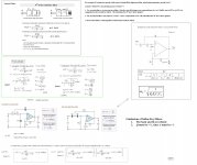
Hi, Agree 100%.....Picking 'F & Q & G' are all that's needed HR should apply proper TF's, all of Unity gain.
Made a 'cut and paste' picture to ponder on....:
b
")
Attachments
Just letting you know that because of the unprecedented interest shown in the matter, I have started developing a filter wizard for Hornresp.

GM
Hi Everyone,
The more information you give me, the more confused I become.
At this stage, I think I will just go ahead with my original idea for active filters. Once people get a chance to use the Wizard, if someone can then provide me with actual generalised formulas describing filters in the way that you want, then perhaps I can add them in later as options.
As an example of the sort of thing I would be looking for, the normalised gain at frequency f for a low-pass Linkwitz-Riley filter is given by the expression:
G = 1 / (1 + (f / fc) ^ n)
Where fc = filter cutoff frequency and n = filter order.
As I have indicated on previous occasions, filters are not really of great interest to me, and my lack of practical knowledge on the subject is now beginning to show.
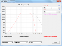
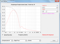
One thing I should perhaps clarify though, is that the proposed Wizard will not design filters for you, it will simply show the effect the filter has on the SPL response and diaphragm displacement of the loudspeaker.
Kind regards,
David
The more information you give me, the more confused I become
.At this stage, I think I will just go ahead with my original idea for active filters. Once people get a chance to use the Wizard, if someone can then provide me with actual generalised formulas describing filters in the way that you want, then perhaps I can add them in later as options.
As an example of the sort of thing I would be looking for, the normalised gain at frequency f for a low-pass Linkwitz-Riley filter is given by the expression:
G = 1 / (1 + (f / fc) ^ n)
Where fc = filter cutoff frequency and n = filter order.
As I have indicated on previous occasions, filters are not really of great interest to me, and my lack of practical knowledge on the subject is now beginning to show
.One thing I should perhaps clarify though, is that the proposed Wizard will not design filters for you, it will simply show the effect the filter has on the SPL response and diaphragm displacement of the loudspeaker.
Kind regards,
David
Last edited:
Originally Posted by David McBean
One thing I should perhaps clarify though, is that the proposed Wizard will not design filters for you,
That's fine & not really required anyway, as there is abundant info already available for that purpose.
it will simply show the effect the filter has on the SPL response and diaphragm displacement of the loudspeaker.
Which is what i was hoping for initially
Don't rush it for our sakes though. It'll be ready when it's ready
Regards
Same goes for me.
All I'm interested in is the ability to see what a filter I make up does to the output properties of a horn or box.
To ask for a wizard that will automatically design a filter is to much at this point.
Please do not feel overwhelmed David.
The very idea that you have accepted the challenge is encouragement enough.
Hi Everyone,
The more information you give me, the more confused I become
At this stage, I think I will just go ahead with my original idea for active filters. Once people get a chance to use the Wizard, if someone can then provide me with actual generalised formulas describing filters in the way that you want, then perhaps I can add them in later as options.
As an example of the sort of thing I would be looking for, the normalised gain at frequency f for a low-pass Linkwitz-Riley filter is given by the expression:
G = 1 / (1 + (f / fc) ^ n)
Where fc = filter cutoff frequency and n = filter order.
As I have indicated on previous occasions, filters are not really of great interest to me, and my lack of practical knowledge on the subject is now beginning to show
One thing I should perhaps clarify though, is that the proposed Wizard will not design filters for you, it will simply show the effect the filter has on the SPL response and diaphragm displacement of the loudspeaker.
Kind regards,
David
Hi David,
In short: Your function is only a correct Magnitude function but will not pass any argument(phase) to other chained Tf's.
For an example let fc=100Hz: Your Equation is basically correct for a first order Bw when n=1 returning a f-3dB at ~41.25Hz or -6dB at 100Hz and when n= 2 or all even order numbers for n is in use:
It returns a correct absolute valued 20 x log (magnitude) = f-6dB value at fc when plotted but you cannot retrieve the corresponding phase function from this equation, i.e. when multiplying with other TF's it would be equal to multiply with a scalar function.
In my last submitted picture the very first expression up left side is a correct low-pass second order TF function with Gain K that can easily be transformed to be equal to your equation when taking the magnitude off when K=1 and by using your n that would equal 2.
b
In short: Your function is only a correct Magnitude function but will not pass any argument(phase) to other chained Tf's.
Hi bjorno,
Thanks for your comments. I had been assuming that with the method I am using, I didn't need to worry about phase
. From tests I have done, the slopes for all the active filter configurations I have allowed for, seem to be as expected. I would certainly appreciate any feedback on the accuracy of the active filter results though, once you get a chance to play with the Wizard.Kind regards,
David
Hornresp Update 3200-130417
Hi Everyone,
CHANGE 1
The limit for the minimum value of Vas has been lowered from 0.01 to to 0.001 litres. See http://www.diyaudio.com/forums/mult...e-bandpass-mid-unity-horn-76.html#post3456342 for background details.
CHANGE 2
The proposed filter wizard tool has been added to Hornresp. It can be accessed from the SPL Response window using the Tools > Filter Wizard menu command.
The following information is taken from the Hornresp Help file, and outlines the available features.
//////////////////////////////////////////////
The initial slider control settings and chart results are saved as reference baselines when the tool is selected. Up to four sets of passive filter values can be stored and recalled by clicking the appropriate memory button or pressing the equivalent function key.
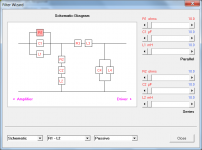
Press the S key to instantly check the schematic diagram.
To change the components in the branch of a passive filter from series to parallel configuration, double-click on the label below the relevant slider group. To change the alignment type of an active filter, double-click on the alignment label. To change the slope units from dB per octave to dB per decade, double-click on the slope label. To change the frequency range, double-click on the chart frequency label. To directly set a slider control to a specified value, key in the value and then press Enter while the control has the focus.
To reset a slider control to its baseline value, press B while the control has the focus. To reset all slider controls for a filter to their baseline values, press Alt+B. To save a new baseline for a filter with the current slider control settings and chart results, press Ctrl+Alt+B.
//////////////////////////////////////////////
The Wizard passive filter results are identical to those produced by AkAbak.
Could you please let me know if you find any bugs, or errors in the active filter results.
Three sample screenprints are attached. For anyone who might be interested, I have also attached a copy of the latest Hornresp version history.
Kind regards,
David
Hi Everyone,
CHANGE 1
The limit for the minimum value of Vas has been lowered from 0.01 to to 0.001 litres. See http://www.diyaudio.com/forums/mult...e-bandpass-mid-unity-horn-76.html#post3456342 for background details.
CHANGE 2
The proposed filter wizard tool has been added to Hornresp. It can be accessed from the SPL Response window using the Tools > Filter Wizard menu command.
The following information is taken from the Hornresp Help file, and outlines the available features.
//////////////////////////////////////////////
The initial slider control settings and chart results are saved as reference baselines when the tool is selected. Up to four sets of passive filter values can be stored and recalled by clicking the appropriate memory button or pressing the equivalent function key.
Press the S key to instantly check the schematic diagram.
To change the components in the branch of a passive filter from series to parallel configuration, double-click on the label below the relevant slider group. To change the alignment type of an active filter, double-click on the alignment label. To change the slope units from dB per octave to dB per decade, double-click on the slope label. To change the frequency range, double-click on the chart frequency label. To directly set a slider control to a specified value, key in the value and then press Enter while the control has the focus.
To reset a slider control to its baseline value, press B while the control has the focus. To reset all slider controls for a filter to their baseline values, press Alt+B. To save a new baseline for a filter with the current slider control settings and chart results, press Ctrl+Alt+B.
//////////////////////////////////////////////
The Wizard passive filter results are identical to those produced by AkAbak.
Could you please let me know if you find any bugs, or errors in the active filter results.
Three sample screenprints are attached. For anyone who might be interested, I have also attached a copy of the latest Hornresp version history.
Kind regards,
David
Attachments
....and, moments later - I may have a bug to report.
It appears that the Filter Wizard baseline is not refreshing when a new record is loaded. I can easily set a new baseline with Ctrl-Alt-B however, so I do not know if this is intentional or not.
Regardless - thank you for the enhanced functionality.
It appears that the Filter Wizard baseline is not refreshing when a new record is loaded. I can easily set a new baseline with Ctrl-Alt-B however, so I do not know if this is intentional or not.
Regardless - thank you for the enhanced functionality.
It appears that the Filter Wizard baseline is not refreshing when a new record is loaded.
Hi littlemike,
This was done intentionally, to preserve existing slider settings when the record is changed (because the Wizard settings cannot be permanently saved to a record, as mentioned in a previous post). I take your point, though - it is confusing. With hindsight, perhaps I could de-couple the baseline charts and the sliders, and allow for the baseline charts to be updated in accordance with the new record, but leave the slider settings unchanged. I will investigate further.
Many thanks for the feedback.
Kind regards,
David
Hello David.
You are great!!
I took a quick look, this is great. Here are my quick findings and thoughts:
- Would it be possible to have active and passive filtering active at the same time?
- In the filter wizard, it says "series" on both slider tripllets. X-Over design ususllay refers to "serial" and "parallel" elements, the R1,C1,L1 being the one in series to the driver, the R2,C2,L2 in parallel (although the later three are in series to each other, yes..).
- Could the Filter Wizard show the impedance? When doing passive crossovers, its sometimes very important not to get a too low impedance.
- How about a little "reset" and "range" button to set sliders to zero or high values? When doing a highpass C for a Subwoofer (used sometimes in Home Cinema and Hifi Speakers), one needs very high values of up to 2000 yC.
-On active Filtering: Could acoustical Phase be displayable? For setting xovers, it would help.
I really love that filters are stored over several projects, this way we can "take the filters to another box". To store them somehow would be nice in cases of complex passive networks, but this is so nice already
Thank you!!
You simply cannot forget the role of the phase whatever active or passive filtering.
Hi Jean-Michel,
Would it be possible to check in some way, if my method is producing incorrect results?
From comparison tests I have done with AkAbak, the passive filter predictions seem fine.
Kind regards,
David
- Would it be possible to have active and passive filtering active at the same time?
- In the filter wizard, it says "series" on both slider tripllets. X-Over design ususllay refers to "serial" and "parallel" elements, the R1,C1,L1 being the one in series to the driver, the R2,C2,L2 in parallel (although the later three are in series to each other, yes..).
- Could the Filter Wizard show the impedance? When doing passive crossovers, its sometimes very important not to get a too low impedance.
- How about a little "reset" and "range" button to set sliders to zero or high values? When doing a highpass C for a Subwoofer (used sometimes in Home Cinema and Hifi Speakers), one needs very high values of up to 2000 yC.
-On active Filtering: Could acoustical Phase be displayable? For setting xovers, it would help.
Hi Sabbelbacke,
Unfortunately, because of the way that the wizard is constructed, most of the features you are requesting cannot be readily implemented. I am trying to keep things as simple as possible - mainly because I don't want to spend too much time working on something that doesn't particularly interest me
.To address your specific points:
* Active and passive filtering together would require too much work to implement
.* The "series" labels refer to the configuration of the components in each of the four branches. The descriptions do not relate to the positioning of the branches themselves in the overall network. Double-click on the labels to change from series to parallel.
* By impedance, do you mean the magnitude of the total electrical input impedance looking into the passive filter, when it is connected to the speaker?
* To set a slider to zero or to a high value, simply enter the required value directly, as explained in the Help file.
* Displaying acoustical phase would require too much work to implement
.Kind regards,
David
Ok. If it were not too much work, it would have been niceUnfortunately, because of the way that the wizard is constructed, most of the features you are requesting cannot be readily implemented. I am trying to keep things as simple as possible - mainly because I don't want to spend too much time working on something that doesn't particularly interest me
Should have read the read-me before playing around* The "series" labels refer to the configuration of the components in each of the four branches. The descriptions do not relate to the positioning of the branches themselves in the overall network. Double-click on the labels to change from series to parallel.
The one seen by the amplifier, yes.* By impedance, do you mean the magnitude of the total electrical input impedance looking into the passive filter, when it is connected to the speaker?
The one seen by the amplifier, yes.
Hi Sabbelbacke,
Thanks for the clarification. I will see what I can do
.Kind regards,
David
- Home
- Loudspeakers
- Subwoofers
- Hornresp