Hi David,
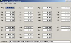
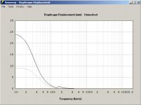
I took a simple dual driver sealed box (modeled in Nd), and slot-loaded the front of the driver using OD. While most graphs look as expected, the displacement at the low end looks too large, e.g.: @ 15Hz it almost tripples. I don't have any way to physically verify this; but, does that seem correct to you? Additionally, the impulse response shows a stronger than expected ringing; and, why do both curves not start at the same time, I would not have thought that there should be a 5msec difference here?
I'm wondering about the correctness of the simulations.
Regards,
Attachments
Last edited:
While most graphs look as expected, the displacement at the low end looks too large, e.g.: @ 15Hz it almost tripples.
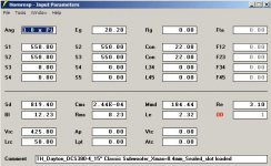
Try using the same number of drivers for both simulations. I see that your closed box sim has two drivers in series, while the slot-loaded version has only one.
-Bjørn
Hi Bjorn,
Thank you so much. Sometimes I can look at something like this, and just cannot see the obvious. This fixes the displacement (I knew that could not be right), but the SPL and the impulse response still look bad, and I still don't understand why there should be a substantial difference in the first arrival time?
Regards,
I took a simple dual driver sealed box (modeled in Nd), and slot-loaded the front of the driver using OD. While most graphs look as expected, the displacement at the low end looks too large, e.g.: @ 15Hz it almost tripples. I don't have any way to physically verify this; but, does that seem correct to you? Additionally, the impulse response shows a stronger than expected ringing; and, why do both curves not start at the same time, I would not have thought that there should be a 5msec difference here?
Hi Oliver,
As far as I can determine, the Hornresp simulation results should be valid
") .
.As Bjørn has pointed out, changing to 2S drivers in the offset driver horn example will resolve the displacement issue.
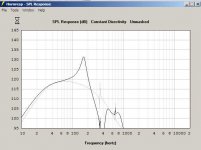
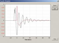
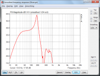
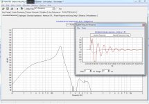
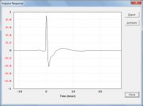
The SPL response (resonances unmasked) and the impulse response ringing are what I would expect to see for the offset driver horn configuration you have specified. Sanity check - when the impulse response is exported to ARTA and transformed back to the frequency domain, the resulting SPL response is very close to the original (see attached screenprints).
As documented in the Impulse Response tool description in the Hornresp Help file, the maximum positive or negative amplitude value is normalised to 0.9 and the maximum peak is positioned by default at the 0 msec reference point. This was the presentation recommended to me by Jean-Michel (Jmmlc), the author of the impulse response calculation method used in Hornresp.
In the case of your offset driver horn example, the maximum peak is negative which is why it, rather than the first positive spike, is shown at the 0 msec point.
Hope this helps to clarify things.
Kind regards,
David
Attachments

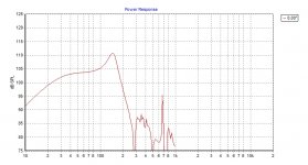
To confirm the simulations, I ran the same setup in my own horn simulation SW, and got the same results (but then I use the same model... ). A use a different IR calculation algorithm, and I do not change the position of the impulse based on the location of the peak. Still the results are very similar.
The dip at around 390Hz comes from the fact that the L12 is a quarter wavelength at that frequency, so the reflection from the blocked end is 180 degree out of phase with the driver. The front acoustical load impedance is as good as zero at this frequency.
The peak at ~160hz is at the quarter wave resonance frequency of the full length of the horn plus end correction, which is about 10cm. There is a large peak in the acoustical impedance at this frequency, raising the efficiency by around 10dB compared to the 30-100Hz range.
The model assumes the driver to be attached at a *point*, in practice it will be "distributed". That will most likely change the magnitude of the peaks and dips, especially since the slot is relatively shallow, and the driver occupies a large part of it.
A 2D BEM simulation (free field, 3m distance) gives a very similar result, but with a somewhat less pronounced peak. So the Hornresp simulation appears to be quite good
-Bjørn
). A use a different IR calculation algorithm, and I do not change the position of the impulse based on the location of the peak. Still the results are very similar. The dip at around 390Hz comes from the fact that the L12 is a quarter wavelength at that frequency, so the reflection from the blocked end is 180 degree out of phase with the driver. The front acoustical load impedance is as good as zero at this frequency.
The peak at ~160hz is at the quarter wave resonance frequency of the full length of the horn plus end correction, which is about 10cm. There is a large peak in the acoustical impedance at this frequency, raising the efficiency by around 10dB compared to the 30-100Hz range.
The model assumes the driver to be attached at a *point*, in practice it will be "distributed". That will most likely change the magnitude of the peaks and dips, especially since the slot is relatively shallow, and the driver occupies a large part of it.
A 2D BEM simulation (free field, 3m distance) gives a very similar result, but with a somewhat less pronounced peak. So the Hornresp simulation appears to be quite good
-Bjørn
Attachments
Hi David and Bjorn,
Thank you both, your explanations are very much appreciated.
I was looking at this thread: http://www.diyaudio.com/forums/subwoofers/223960-bench-style-cabinet-subwoofer-2x15-closed-3.html Post #23, and wondered about this application of slot-loading.
As djk has pointed out numerous times in the PPSL thread: http://www.diyaudio.com/forums/subwoofers/177905-thread-those-interested-ppsl-enclosures.html e.g.: Post #6, the cavity resonances reduce a lot when one of the drivers is turned around (and even more, if the S1 area of the slot is partially filled in).
Again, Hornresp is just a wonderful tool. Save a tree - simulate.
Regards,
hi david
is there any sofware that you (or anybody else)now of ,that can import hr data ,to model a filter/eq .
this would be helpfull to determen a hpf.
tnx erik
Hi epa,
Thats easy to do: You only need to convert the HR textfile to a format that any of these program can recognize:
FRD Consortium
PS: I usually first import the .wav files from HR to HOLMimpulse where I edit the IR/FR and then export to e.g. MPRM program where you can do all filtering/ Eq. and the back to Holmimpulse to present the resulting graphs you want to display.
b

The dip at around 390Hz comes from the fact that the L12 is a quarter wavelength at that frequency, so the reflection from the blocked end is 180 degree out of phase with the driver.
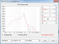
The effect of varying the driver offset position while maintaining a constant overall horn length can be seen by moving the L12 slider in the Loudspeaker Wizard tool. Attachment 1 refers.
The peak at ~160hz is at the quarter wave resonance frequency of the full length of the horn plus end correction, which is about 10cm. There is a large peak in the acoustical impedance at this frequency, raising the efficiency by around 10dB compared to the 30-100Hz range.
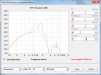
The effect of varying the overall horn length while maintaining a constant driver offset position can be seen by moving the L23 slider in the Loudspeaker Wizard tool. Attachment 2 refers.
The model assumes the driver to be attached at a *point*,
If Nd is set to 1 in the sealed box example, and in the offset driver example S1 to S3 are set to 819.40 (Sd) and L12 and L23 are set to 0.01, then the results for the two cases become effectively identical, as expected.
Kind regards,
David
Attachments
Thank you both, your explanations are very much appreciated.
Hi Oliver,
Please continue to query any Hornresp results that may seem a little strange.
It prompts me to conduct further tests to ensure that the simulation models are indeed operating correctly
.Kind regards,
David
how do i export*.wav from hr?
Hi epa,
Select the Tools > Impulse > Response menu command from the SPL Response chart window, and then click the Export button.
Kind regards,
David
Attachments
Last edited:
@Björn
Returned from work after daaaaays and just clicked your screenshot.... What nice looking peace of software ist this you are building there?
It's a horn simulation SW
When I started going really deep into horn theory some years ago, I also started writing horn simulation SW to better understand the physics involved. While I had Hornresp, I both wanted to understand what was going on behind the scenes, and to try some of my own ideas. Over the years (since early 2006) it has evolved to a quite complex program that does most of what Hornresp does, plus and minus some things. David and I have had quite a lot of discussion and exchange of ideas about horn simulation over the years, and David has helped me a lot, especially in the beginning. I hope I have contributed to some useful features in Hornresp in return
The plan is to release HornCAD to the public some day, but it will not be freeware for two reasons: We already have an excellent piece of free horn SW in Hornresp, and it is not my intention to compete with it. The other reason is that I have a day job, and if I am to provide support anywhere near the level of Hornresp, I need to get paid for the time I spend.
However, I could use a couple of Beta testers
-Bjørn
If I can help I would be pleased to be a tester.
Thanks, Mark. You've got a PM
Please, could someone model this for me? I am too stupid to learn Hornresp, I downloaded it and tried to, really!
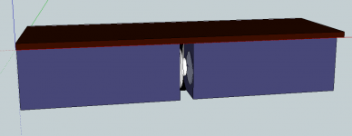
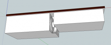
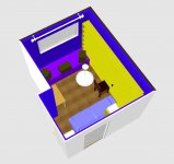
tb46 already tried to simulate my plans of a ppsl sub which has it's own thread here http://www.diyaudio.com/forums/subwoofers/223960-bench-style-cabinet-subwoofer-2x15-closed.html and final plans from message #25 on. SEe attached sketches below.
I'll use two Dayton Classic 15" drivers in series, connected push-pull in separate identical 258 liter closed boxes.
The slot plenum is 100mm wide and 420mm high, max depth is 420mm but the rear side of it is rouded with a hemispherical filling. Plenum opening area is 420 cm2 and it is on floor level in a 10,5 m2 room (2,6x3,65x2,55m). The edge of top board makes a 25mm lip on top of the plenum, the board is 40mm thick.
Thank You in advance,
Juha
Attachments
Last edited:
However, I could use a couple of Beta testers
Now I have my Beta testers, I think two is enough for starters. Thanks, guys!
-Bjørn
Hornresp Update 3010-121125
Hi Everyone,
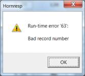
Opening the Data File Editor and selecting a file name but then cancelling out of the tool without saving, could sometimes cause the attached fatal error to be generated when later navigating through the Hornresp records.
This bug has now been fixed.
Kind regards,
David
Hi Everyone,
Opening the Data File Editor and selecting a file name but then cancelling out of the tool without saving, could sometimes cause the attached fatal error to be generated when later navigating through the Hornresp records.
This bug has now been fixed.
Kind regards,
David
Attachments
- Home
- Loudspeakers
- Subwoofers
- Hornresp