Helmuth said:Only I can not find the tapped horn wizard
Hi Helmuth,
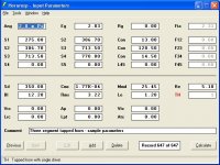
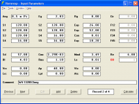
Try using the input parameter values shown in the attached example, if you are still having difficulties activating the Tapped Horn Wizard menu command.
Kind regards,
David
Attachments
Re: Phase plugs and other wierdness.
Hi screamersusa,
Just confirming that Hornresp makes no special provisions for a phasing plug. The actions you propose seem reasonable.
Kind regards,
David
screamersusa said:Aside from subtracting the area from S1 and the throat, that the phase plug occupies, are there any other tweaks I should know about that are hidden in horn resp for such a situation?
Hi screamersusa,
Just confirming that Hornresp makes no special provisions for a phasing plug. The actions you propose seem reasonable.
Kind regards,
David
David McBean said:
Hi Helmuth,
Try using the input parameter values shown in the attached example, if you are still having difficulties activating the Tapped Horn Wizard menu command.
Kind regards,
David
Thanks David,
It works and it is really great.

How can you make such a nice program are you programmer with a audio hobby?
It would be nice if also the total volume is shown when that would be possible. Because when simulating this is one of my biggest
 problems.
Regards Helmuth.Lageschaar
Attachments
Helmuth said:Are you programmer with a audio hobby?
It would be nice if also the total volume is shown when that would be possible.
Hi Helmuth,
I am a retired electrical engineer and self-taught amateur programmer, with a long-standing interest in horn loaded loudspeakers.
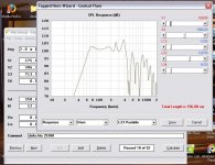
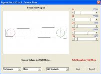
As Johan has mentioned, the system volume is shown on both the Tapped Horn Wizard schematic diagram (see attached) and the main program schematic.
Kind regards,
David
Attachments
Hi David,I am a retired electrical engineer and self-taught amateur programmer, with a long-standing interest in horn loaded loudspeakers.
Sorry about not looking good enough.(bedankt johan)
I am really curious how calculation of the SPL is determined. I have seen formulas how calculate the horn not the gain.
Some times I can not believe the SPL witch is calculated when I am using a low SPL speaker.
And know the gain of floor wall and corner.
Can you tell something about it David?
Regards Helmuth
The tutorial is now fully updated.David McBean said:
Hi aznboi3644,
The only Hornresp tutorial I am aware of is located at http://www.diyaudio.com/wiki/index.php?page=Hornresp+Help
It's a bit dated now, and some of the input parameter names have changed, but it still may be of some use.
I was not involved in setting up the web page.
Incidentally, it's real easy to get started in Hornresp - just click the 'Calculate' button to see how the program operates with the default record, or click the 'Add' button if you wish to create and edit your own new record
Kind regards,
David
Edit - Tho still looking for a reliable image hosting. -
Best regards Johan
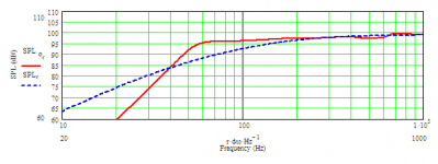
Helmuth said:I am really curious how calculation of the SPL is determined.
Hi Helmuth,
For a conventional horn loaded loudspeaker, Hornresp first calculates the acoustical impedance of the air load on each side of the driver diaphragm, and then analyses the standard electro-mechano-acoustical loudspeaker equivalent circuit to find the power radiated from the horn-facing side of the diaphragm. The horn is assumed to have no transmission losses.
For the purposes of calculating constant directivity SPL, the loudspeaker is assumed to be a point source. The sound intensity is taken at the surface of a 1 metre radius sphere centred on the source. It is standard industry practice to normalise SPL response results in this way so that the performance of different loudspeaker configurations can be directly compared.
Once the intensity is known, the pressure and SPL at the 1 metre reference point can be calculated.
To illustrate the process using a specific example, calculate the SPL response for the Hornresp default record number 1 and sample at 100 hertz. You will see that the acoustical output power is calculated to be 0,2935 watts.
Surface area of sphere = 4 * Pi * Radius ^ 2 square metres. Because Ang = 0,5 x Pi for the default example, radiation into eighth space only is required.
Therefore Area = (4 * Pi * 1 ^ 2) / 8 = 1,5708 square metres
Intensity = Power / Area = 0,2935 / 1,5708 = 0,1868 watts / square metre
Pressure = (Intensity * Density * Velocity) ^ 0,5 newtons / square metre
Assuming density of air = 1,205 kilograms / cubic metre and velocity of sound = 344 metres / second
Pressure = (0,1868 * 1,205 * 344) ^ 0,5 = 8,7996 newtons / square metre
SPL = 20 * Log10(Pressure / Reference pressure)
Reference pressure = 2 * 10 ^ -5 newtons / square metre
SPL = 20 * Log10(8,7996 / (2 * 10 ^ -5)) = 112,8687 dB
The reason for the slight discrepancy from the actual 100 hertz sample result of 112,8696 dB is simply because the acoustical output power figure and all intermediate calculation results used in the above example have been rounded to 4 decimal places for the sake of convenience.
Analysing a tapped horn is a bit more complicated in that the power radiated from both sides of the diaphragm needs to be taken into account when calculating the SPL response.
Hope this helps.
Kind regards,
David
Rademakers said:The tutorial is now fully updated.
Hi Johan,
Many thanks for providing this supplementary information on how to use Hornresp.
Kind regards,
David
Cool, could you send me your e-mail adress?Sabbelbacke said:Hy Johann, I could host pictures, I have a few gig of traffic per month left over, should suffice for a few pics in a tutorial.
@David: If you stop improving your program all the time it will be up to date for ever
Best regards
Hi David,
Thanks for explaining this so detailed.
I have red the explanation three times but I do not fully understand everything. What I ask my self when I design a back loaded horn.
The calculated SPL then is much higher then the SPL of the speaker. So I do conclude this will no work properly at higher frequencies.
Is this correct David.
Helmuth said:What I ask my self when I design a back loaded horn. The calculated SPL then is much higher then the SPL of the speaker. So I do conclude this will no work properly at higher frequencies.
Hi Helmuth,
Hornresp does not take directivity effects into account when modelling a back loaded horn loudspeaker. At higher frequencies the actual on-axis output from the direct radiator side of the diaphragm will be somewhat greater than predicted due to a narrowing of the beam width as the frequency increases. This means that the combined on-axis response should be better than that given in the simulation.
Kind regards,
David
Hi David,
It is the Tractrix-man from audioasaylum speaking !
Did a few sims with a small ML TQWT called Tabaq. The speaker is from the beginning modeled in MJKs worksheets with a small Tangband.
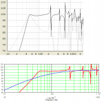
These are repective results. Both undamped. The difference is that Hornresp predicts a lower resonance-point. Please comment as I find this very interesting.
One difference is that in the worksheets you can add damping at whatever part of the line you want, to see how this affects resonaces etc.
It is the Tractrix-man from audioasaylum speaking
!Did a few sims with a small ML TQWT called Tabaq. The speaker is from the beginning modeled in MJKs worksheets with a small Tangband.
These are repective results. Both undamped. The difference is that Hornresp predicts a lower resonance-point. Please comment as I find this very interesting.
One difference is that in the worksheets you can add damping at whatever part of the line you want, to see how this affects resonaces etc.
Attachments
revintage said:The difference is that Hornresp predicts a lower resonance-point. Please comment as I find this very interesting.
Hi Lars,
I must be missing something
. Both the undamped frequency response charts in your comparison have a low frequency roll-off at about 55 hertz, and the higher frequency resonance spikes are all in effectively the same places. Where is the difference?Kind regards,
David
revintage said:When I read it -3dB in Hornresp is 45 and MJK is at least 50Hz. This means ca 10% diff.
Hi Lars,
I suspect that it may have something to do with the way that eighth-space loading is modelled by the two programs. Is there much of a difference in the results when the radiation angle is changed to 2 Pi half space?
How do the individual responses from the front and rear sides of the diaphragm compare?
Kind regards,
David
- Home
- Loudspeakers
- Subwoofers
- Hornresp