Define "perform well".A question: Can a 500Hz horn be folded and still perform well up to that frequency?
The vast majority of speech horns are folded, AKA "re-entrant" horns, some sound and measure quite well.
A large re-entrant horn can cover from as low as 200 Hz to upwards of 5000 Hz with a thread on 1 inch exit driver.
Folding will always cause some extra dips and peaks in the response compared to a straight horn.
Fold it right, using appropriate reflectors for the frequency range required, and the peaks will not be large, while the ear is not particularly sensitive to narrow dips.
It can be argued that the dips and peaks caused by reflections from room surfaces when using direct radiators are more objectionable than a peaky horn which because of it's directivity avoids those reflections.
Yes, there will be more 1/4 space gain below 130 Hz, but above that there will not be an abrupt change like a light turning on or off, think more in terms of multiple lights dimming on and off all throughout the room.If you have a horn that is about 65 cm deep and put it on the floor backed up against a wall, the 1/4 wave frequency from the mouth to the wall is about 130 Hz (65 cm x4 = 260 cm, the wavelength of 130 Hz). So, as I'm trying to figure out how this stuff works, I thought that the horn would "see" the wall at frequencies below 130 Hz, and then the wall would be invisible above that frequency. So, if that's the case then I was wondering what would happen if the horn was becoming directive (less than omnidirectional radiation pattern) at some higher frequency than 130 Hz. I don't even know how to figure out the directivity with frequency for a horn without Hornresp. I've used the wavefront simulator in Hornresp to investigate how these things behave with various walls, but I don't know if the simulation is accurate. Hornresp doesn't simulate folded rectangular horns either, so I don't know what happens with that.
The only horns that are easy to figure dispersion for are those with conical expansion, above the frequency where the mouth equals a wave length or so the -6 dB point will be very close to the side wall angle. Below that frequency, the horn will gradually widen in dispersion due to diffraction.
Exponential, hyperbolic, etc. all will narrow in dispersion as the frequency rises, but will also gradually widen in dispersion below the frequency where the mouth approximately equals a wavelength.
A horn like the LaScala will have a dispersion pattern that varies wildly with frequency both horizontally and vertically.
Of course, that didn’t stop it from being popular...
OK, I tried something different in Hornresp. I tried a back loaded horn for the B&C 12PE32 driver, since I have 2 of them. I'm not sure of the design procedure for back loaded horns that are intended to augment the bass response of a particular driver. I found Martin King's website: Quarter Wavelength Loudspeaker Design but I'm not sure he has a design procedure that I can use. Based on the SPL response in Hornresp, a back loaded horn for this driver does not look promising.
I think my only rational choice is a straight 100Hz hyp-ex horn designed for 1Pi space. Length without rear chamber is 82 cm. Mouth is 2354 sq cm (48.5 cm square). The -3dB points are 100 Hz and 700 Hz, according to the simulation. The higher frequencies shouldn't be a problem with a straight horn.
Honestly, if this horn is going to be in a normal sized residential room, a bigger question might be how the horn will behave based on the dimensions of the room and its location in the room as opposed to its proximity to boundaries.
Yeah, I don't know how to figure that out.
Originally Posted by John Sheerin
Honestly, if this horn is going to be in a normal sized residential room, a bigger question might be how the horn will behave based on the dimensions of the room and its location in the room as opposed to its proximity to boundaries.
At low volume, a cardboard and duct tape horn (with an over-sized compression chamber allowing for different fill blocks to be put in) can give a good idea of what the response will be without buying wood.
Honestly, if this horn is going to be in a normal sized residential room, a bigger question might be how the horn will behave based on the dimensions of the room and its location in the room as opposed to its proximity to boundaries.
You build the cabinet, then listen and measure ;^).Yeah, I don't know how to figure that out.
At low volume, a cardboard and duct tape horn (with an over-sized compression chamber allowing for different fill blocks to be put in) can give a good idea of what the response will be without buying wood.
Originally Posted by John Sheerin
Honestly, if this horn is going to be in a normal sized residential room, a bigger question might be how the horn will behave based on the dimensions of the room and its location in the room as opposed to its proximity to boundaries.
You build the cabinet, then listen and measure ;^).
At low volume, a cardboard and duct tape horn (with an over-sized compression chamber allowing for different fill blocks to be put in) can give a good idea of what the response will be without buying wood.
HAHA...

Putting this horn back up against a wall isn't going to help much since the mouth is going to be more than a 1/4 wavelength for virtually all of the intended response range. As you might expect, the directivity pattern for this 1/4 size horn in 1/2 space is omnidirectional up to at least 500 Hz. That's not going to be very helpful for good sound. Short of reconstructing the room by building a wall that can accommodate flush mounting of the horn mouths, there isn't much I can do about this.
Just downloaded V2870-111016, and all looks better.
Hi Oliver,
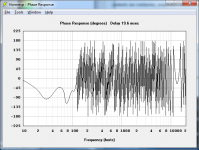
You may have noticed that with some loudspeaker designs there is a 180 degree phase difference between the standard wrapped phase with zero delay, and the corrected phase with an offset delay of 0.1 msec.
This will be addressed in the next release. Changing from zero to 0.1 msec delay will no longer have the potential to generate a phase reversal discontinuity.
Also, sometimes the sampled phase results for 1 hertz and 2 hertz are incorrect. This will be fixed at the same time.
Kind regards,
David
I'm guessing this is a bug, but I'm not sure.
Hi aackthpt,
Thanks for the feedback.
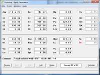
The delay-corrected phase response shown in your screenprint looks about right for a tapped horn having a length of 584 cm.
What aspect of the result is causing you concern?
Kind regards,
David
Hornresp Update
Hi Everyone,
The changes referred to above have now been implemented.
The latest Hornresp release is Product Number 2870-111022.
Kind regards,
David
Hi Everyone,
To make things a bit clearer I will change the column headings from X and Y to Length and Radius in the next release. This will then also make them consistent with the headings used for the other two Le Cléac'h horn schematic diagram export options.
This will be addressed in the next release. Changing from zero to 0.1 msec delay will no longer have the potential to generate a phase reversal discontinuity. Also, sometimes the sampled phase results for 1 hertz and 2 hertz are incorrect. This will be fixed at the same time.
The changes referred to above have now been implemented.
The latest Hornresp release is Product Number 2870-111022.
Kind regards,
David
Phase is 180 degrees different in new version?
Has anyone else noticed this?
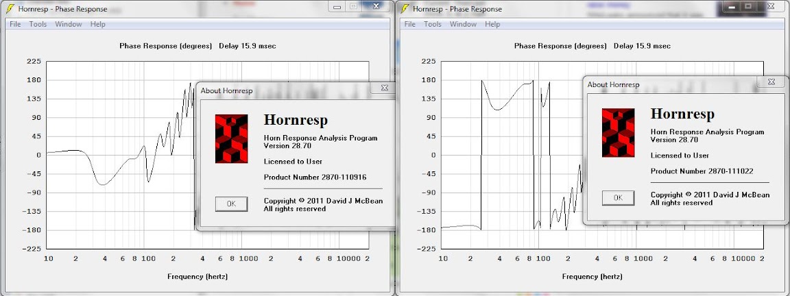
New version of Hornresp on the right, previous version on the left.
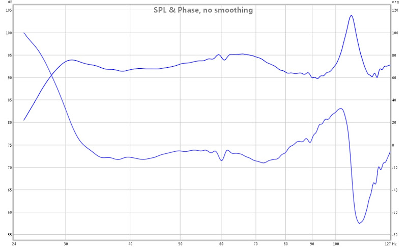
This is my T-6 tapped horn, the exact same record was used in each version. My actual measurement of this design (acoustic phase, groundplane, 1 meter) looked a lot more like the plot on the left.
It looks like there is a 180-degree change between versions here.
Has anyone else noticed this?
New version of Hornresp on the right, previous version on the left.
This is my T-6 tapped horn, the exact same record was used in each version. My actual measurement of this design (acoustic phase, groundplane, 1 meter) looked a lot more like the plot on the left.
It looks like there is a 180-degree change between versions here.
It looks like there is a 180-degree change between versions here.
Hi littlemike,
The phase reversal is due to the second change advised in my Post #2332.
Could you please post a screenprint of your input parameters window so that I can investigate further. Thanks.
Kind regards,
David
Hello David,
I remember to have introduced in the code of the phase/delay module of Hornresp a test which check the polarity. When a polarity inversion is detected then a phase inversion is performed. Seems that this procedure is fooled in the last version.
Also, some previously mentionned phase problems may occur when both a front and a rear wave interfer. If an inverse polarity for the front wave is detected then the phase inversion should be applied to both the front wave and the rear wave.
But the problem could have another origin...
Best regards from Paris, France
Jean-Michel Le Cléac'h
Hi all,
I've been using BBP for years and find this a very easy programme for me to use. Recently I've decided to look into tapped horns and downloaded hornresp-to say I'm baffled would be an understatement! I'm dyslexic and not only do the abreviations for everything confuse the bejesus out of me but the lack of a visual "box" also make it hard for me to mentally picture how my inputs relate to the horn I'm trying to design.
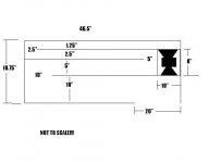
I have two KEF B139 that I'm trying to design a horn for, for a fixed space under a sideboard at home, gross dimensions available are: 46.5"w x 16.5"h x18.75"d. I live in a tiny house-so please do not suggest any other designs as this is the only space I can allocate to the enclosure.
I plan to mount the drivers isobarically mag-2-mag (to use the mags as bucking mags, old CRT sat above enclosure). The face of one subwoofer will be at the throat, the face of the other in the mouth. The enclosure I mentally came up with is pictured (crudely) below and the T/S specs I've pulled of the drivers are below, averaged from the two drivers and then the net figure from wiring the speakers in parallel to get down to a 4ohm load for my amplifier:
Fs: 28.94
QMS: 0.44
VAS: 59.3 net 29.65litres
CMS: 0.4 net 0.2
MMS: 75.34 net 150.7grammes
RMS: 31.25 net 62.5
SD: 323.1cm2
QES: 0.645
RE: 7.12 net 3.56
BL: 12.3tm
QTS: 0.262
No: 0.215 net 0.1075
SPL1w/1m: 85.37dB net 82.36dB
SPL 2.83V: 86.03dB net 86.03dB
Now for the favour: could someone input the above with the dimensions below and take a screen shot of it? From there I hope my brain will kick in and I'll be able to contiue with the design-if not I'll know it's off to the nursing home at 33yrs old Box will either radiate straight into the room (on the floor) or into a bay window (this being preferable as my 7month old will be crawling soon and the 20"x15" opening would be large enough for her to disapear into!) NB: I plan to use .75" MDF all round-as I have a load lying around and little baby=BIG MONEY, so can't go all out on this 1st tester box.
Thanks in advance!
I've been using BBP for years and find this a very easy programme for me to use. Recently I've decided to look into tapped horns and downloaded hornresp-to say I'm baffled would be an understatement! I'm dyslexic and not only do the abreviations for everything confuse the bejesus out of me but the lack of a visual "box" also make it hard for me to mentally picture how my inputs relate to the horn I'm trying to design.
I have two KEF B139 that I'm trying to design a horn for, for a fixed space under a sideboard at home, gross dimensions available are: 46.5"w x 16.5"h x18.75"d. I live in a tiny house-so please do not suggest any other designs as this is the only space I can allocate to the enclosure.
I plan to mount the drivers isobarically mag-2-mag (to use the mags as bucking mags, old CRT sat above enclosure). The face of one subwoofer will be at the throat, the face of the other in the mouth. The enclosure I mentally came up with is pictured (crudely) below and the T/S specs I've pulled of the drivers are below, averaged from the two drivers and then the net figure from wiring the speakers in parallel to get down to a 4ohm load for my amplifier:
Fs: 28.94
QMS: 0.44
VAS: 59.3 net 29.65litres
CMS: 0.4 net 0.2
MMS: 75.34 net 150.7grammes
RMS: 31.25 net 62.5
SD: 323.1cm2
QES: 0.645
RE: 7.12 net 3.56
BL: 12.3tm
QTS: 0.262
No: 0.215 net 0.1075
SPL1w/1m: 85.37dB net 82.36dB
SPL 2.83V: 86.03dB net 86.03dB
Now for the favour: could someone input the above with the dimensions below and take a screen shot of it? From there I hope my brain will kick in and I'll be able to contiue with the design-if not I'll know it's off to the nursing home at 33yrs old
Box will either radiate straight into the room (on the floor) or into a bay window (this being preferable as my 7month old will be crawling soon and the 20"x15" opening would be large enough for her to disapear into!) NB: I plan to use .75" MDF all round-as I have a load lying around and little baby=BIG MONEY, so can't go all out on this 1st tester box.Thanks in advance!
Attachments
Last edited:
Hi littlemike,
The phase reversal is due to the second change advised in my Post #2332.
Could you please post a screenprint of your input parameters window so that I can investigate further. Thanks.
Kind regards,
David
Inputs below.
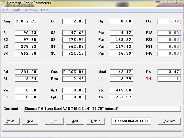
It is not just this model, everything I have worked with lately shows a 180 degree shift. I selected this one because I have measurements of SPL and phase.
Here are the measurements, the speaker and amp were wired in phase. Note that the phase stays near zero, consistent with the older models.
The measured parameters different significantly from the published specs are these drivers modified?
The isobaric configuration is not going to help with a VAS this small I would use them both side by side in a "normal" configuration L12=23
You are in the wrong thread, sombody should move you to the subwoofer thread..
The isobaric configuration is not going to help with a VAS this small I would use them both side by side in a "normal" configuration L12=23
You are in the wrong thread, sombody should move you to the subwoofer thread..
- Home
- Loudspeakers
- Subwoofers
- Hornresp