I'd like to refer to that as different "damping" or "Q".Air speed may be one thing to be aware of, but I'm thinking that air friction (if that's the right description) may be even more relevant in small horns.
The same when one packs a vent tube with straws. The Q has been changed.
I'd like to refer to that as different "damping" or "Q".
The same when one packs a vent tube with straws. The Q has been changed.
Good thinking.
Andrew you are always a source of inspiration.
I have tried the straw trick on ports. The change is usually subtle but there is a change.
Are you thinking the Q idea is a change in the air's compliance?
Is this Off Topic?
But then some other will tell us that there is a g missing. The frivolous discussion might never stop.
lovely phrase, but can I be pedantic and suggest the middle g be replaced with a j?.........thingy magigy...........
But then some other will tell us that there is a g missing. The frivolous discussion might never stop.
Rather than referring to high velocity and low velocity in the horn, I have seen reference in many horn discussions to High Pressure and Low Pressure......... the real world results the air velocity doesn't seem to match up that well either. In horns there is a pattern of high velocity and low velocity movement that will follow the driver displacement roughly. .............
If this a more accurate term then we can expand on it's meaning.
At zero signal the pressures at the throat and the mouth and everywhere else in and around the horn are all equal to atmospheric pressure (atmos) at that altitude, at that time.
Now apply a signal.
The variation in pressure at the throat propagates along the horn to the mouth.
The pressure variation at the (low area) throat are reputed to be much higher than the pressure variations at the (high area) mouth.
Let's assume that the Mouth pressure variations are indeed much less than the throat pressure variations.
Increase the signal level and the throat pressure variations will increase.
At zero signal we have throat pressure = atmos +-0signal.
At normal level output we have atmos +-normal signal.
At high level output we have atmos +-high signal.
I can see no problem with atmos + normal signal nor with atmos + high signal.
I do see a problem with atmos - high signal.
The difference between atmos - normal signal and atmos- high signal could be that the air is changing. Water vapour condensing out, temperature changing or worst case reaching absolute zero pressure.
I really do think it is reduction in pressure limitation that causes the distortion resulting from overdriving the horn.
Last edited:
So a high power stepped sine wave test should get to the bottom of some of this. Say 1/24th octave short duration bursts.
It will excite the horn to a high pressure point and be traceable as to what frequency is of greatest concern in terms of output distortion.
If these things can be correlated to air speed then we ( not me I'm a math imbecile ) may have something useful to model with mathematically.
It will excite the horn to a high pressure point and be traceable as to what frequency is of greatest concern in terms of output distortion.
If these things can be correlated to air speed then we ( not me I'm a math imbecile ) may have something useful to model with mathematically.
Distortion in horns has been researched for a long time. If you search for "horn distortion" in the AES E-Library you'll get lots of hits. (You'll have to pay for the papers if you are not an AES member and have paid for online library access).
The air itself is nonlinear. When the pressure is high, the temperature rises, and the sound travels faster. When the pressure is low, temperature falls, and the sound speed decreases. The result is that the wave peaks gain on the throughs. A sine wave will begin to look more like a sawtooth wave.
I think there are also issues wiht high particle velocity; that the velocity of the signal adds to the velocity of sound, so that the wave "carries itself forward". The result is the same as above, the peaks will move faster than the throughs.
At some point the peaks will overtake the throughs, and you get shock waves. But that is at extremeley high SPLs.
It is possible to model, and that has been done in many of the papers you'll find in the AES library search. But the equations are quite complex.
In the horn throat you'll easily get 130-160dB SPL. To measure distortion at these levels you need a good high-level mic. I use the LinearX M52 Microphone - High Level Low Distortion Measurement Microphone. It's good to 170dB.
Regards,
Bjørn
Kolbrek,
The phenomenon I am interested in most is one where the horns output seemingly plateaus in a few narrow frequency ranges and further increases in power produce no further output gains. This does not happen at areas of high driver excursion but higher up in response. In tapped horns the prominent first spike that is always present (5th harmonic) is one area that always seems to exhibit large amounts of compression and ultimately a complete halt on increased output. Any thoughts?
The phenomenon I am interested in most is one where the horns output seemingly plateaus in a few narrow frequency ranges and further increases in power produce no further output gains. This does not happen at areas of high driver excursion but higher up in response. In tapped horns the prominent first spike that is always present (5th harmonic) is one area that always seems to exhibit large amounts of compression and ultimately a complete halt on increased output. Any thoughts?
Do you mean the first response peak above the pass band? Tapped horns are quite complex electroacoustic systems, so it's not easy to see intuitively where the problem originates. But the internal pressure and volume velocity in a tapped horn is much higher than in the last part from the driver and out. This may be a cause.
Have you noticed similar things in ordinary front-loaded horns? Have you looked at the throat impedance to see if there are any peaks or dips at the frequencies in question? There may be standing waves that build up high internal pressure or velocity values, that you don't see outside the horn.
Just some thoughts.
Bjørn
Thanks for the tips Bjørn
( I figured out how to pull off the ø )
The mic looks interesting.
There are some available from this company to:
PCB Piezotronics, Inc.- Sensors that measure up!
Model:
Model 377A12 Spec Sheet
I think the top end for that capsule is 178 db
Don't know the price on it however.
As for the AES papers.
Yes I have a great deal of catching up to do. I have not dove into the AES pool for about ten years. I had all the relevant information on horns and such up to the late 80's but then I started working in the loudspeaker field. Not enough time in the day. You stop studying full time and you end up working full time.
I think a membership with the AES would make the most sense. Quick and easy and no trip to the library required. Can you download off of the AES site?
As for Josh's comments all I can say is I tried an experiment at a small audio meet here in Ottawa last winter. Four subwoofer designs with all the same driver compliment.
Vented
Front Loaded Horn
Tapped Horn
My weird Unhorn ( quasi bandpass in reality )
From measurements and listening I have to say that the tapped horn (which was a true gain enabling design, it had 7 db of gain not just a tappered pipe) had a great deal of out of passband harmonics. We crossed it over with a fourth order at 80 hz using a behringer DCX as a crossover and DEQ set up as a spl meter and RTA. We tried hard to remove the area in reproduction that created the geatest harmonics and it still was very peaky. Some observers liked it. It imparted a rich overtone to the bass. Not true to signal input. The front loaded horn on the other hand played true to it's roots of high volume and low distortion. Again not a sound that everyone liked. A vented box against those performers did it's best but could not keep up.
Some of the observations can be found here:
http://www.diyaudio.com/forums/clubs-events/176350-winter-diy-ottawa-meet-3.html#post2445138
An attempt to make all things equal was made.
If some correlation between sound pressure and air particle velocity can be made, maybe we will have a useful tool in the design of horns and their physical dimensional aspect ratios. All these things add up to a better design if attention is paid to the correct details.
The phenomenon I am interested in most is one where the horns output seemingly plateaus in a few narrow frequency ranges and further increases in power produce no further output gains.
High aspect ratio ducts are resistive in nature, so more power = more resistance and one reason why auto, etc., mufflers are 'pancaked', so it seems reasonable to me this is what's causing it, tapered, tapped or not.
GM
Attachments
So a high power stepped sine wave test should get to the bottom of some of this. Say 1/24th octave short duration bursts.
It will excite the horn to a high pressure point and be traceable as to what frequency is of greatest concern in terms of output distortion.
If these things can be correlated to air speed then we (not me I'm a math imbecile ) may have something useful to model with mathematically.
Hi Mark,
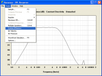
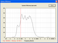
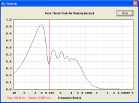
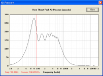
To hopefully assist you in your ongoing investigations, the next Hornresp update will contain three new tools accessible from the SPL response chart window, enabling system efficiency, air velocity and air pressure to be plotted against frequency. Values can also be sampled at specified frequencies, as shown in the attached screenprints.
The update will be released sometime later this week.
Kind regards,
David
Attachments
Hi Mark,
To hopefully assist you in your ongoing investigations, the next Hornresp update will contain three new tools accessible from the SPL response chart window, enabling system efficiency, air velocity and air pressure to be plotted against frequency. Values can also be sampled at specified frequencies, as shown in the attached screenprints.
The update will be released sometime later this week.
Kind regards,
David
Even though I am not Mark....
Wow.
Thank You!
I think I'm Mark.
Mike you are priceless!
This is going to be so much fun. More toys to play with!
I hope that first off I can get an anemometer that will behave.
Second a proper high spl mike that will behave.
Third I hope that as always David calculation consternation's make real world sense.
I have always wondered if there were concrete reason's why some horn folds behave well and some do not.
I think that I'm going to get a little closer to knowing what is what in terms of a optimally folded and designed horn.
So onward and upward.
The math has been lifted off of my little brain.
That leaves the real world of horn path design and then construction.
I have a job where I have to pull off a 20 hz horn with two eight inch drivers in the smallest space available.
Should I be able to do this successfully this will be very interesting.
Thanks again David.
You truly make my life a lot easier.
And I continue to ask the questions.
Now I can find some of the answers.
Sweet!
Hornresp Version 28.60
Hi Everyone,
Tools that enable system efficiency, sound pressure (previously called air pressure) and particle velocity (previously called air velocity) charts to be displayed have now been added to Hornresp. The tools are available under the SPL response window. Click on the charts to sample at a specified frequency (press the Esc key to remove sampling).
Please let me know if you find any bugs.
Kind regards,
David
I have been playing with the new version for a little while.
This is really interesting.
I have been comparing a horn path shape I have optimized versus the same horn done through best calculation methods. As in Hornresp spits out an ideal horn.
The differences are very informative.
And I have a couple of ideas of where the greatest difference can be made in the horns usable pressure bandwidth.
Particle velocities are amazingly fast depending on the horn's area. So I think that is where I will start off simulating the differences.
Josh when you get to play with this I'd be interested in your observations as you have pushed your horns hard as well.
A bit more modeling will get to the point where I want to build a box.
Is there any way to run more than one Hornresp at once?
Make a second copy of the 3 Hornresp files in a different folder. (Hornresp.exe, Hornresp.dat, msvbm60.dll) You can then start both copies.
You will need to use import/export to keep the two copies of hornresp.dat in sync. Or you can make any changes you want to save in one copy, then exit both and copy the hornresp.dat from one to the other. Be careful and keep backups, sooner or later you will mess it up...
One thing I often do for comparing graphs in Hornresp is to use Paint, the basic image editor included in Windows.
- Produce a graph in Hornresp.
- Capture it to clipboard (Alt-PrintScreen).
- Start Paint, paste (Ctrl-C).
- Produce another graph in Hornresp.
- Capture it to clipboard (Alt-PrintScreen).
- Turn off Draw Opaque in Paint (Image --> Draw Opaque, untick.)
- Paste (Ctrl-c)
- Home
- Loudspeakers
- Subwoofers
- Hornresp