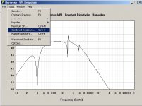
I guess that what you are missing is that hornresp initially shows the output from the driver, without the output from the port.Hi Everyone,
I'm beginning with Hornresp, trying different things.
When simulating a Bass Reflex and comparing the result with WinISD's (to be sure I'm doing ok), I don't get the same response... Could you tell me why ?
I model the same box with the same vent and get two different Helmoltz freq and two different response curves...
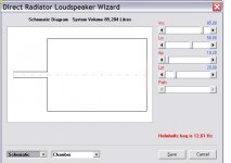
In HR, I did it with the Loudspeaker Wizard (wonderful feature by the way !!)
Perhaps all of this is already explain in this tread, but there's # 2000 messages ! If so tell me where !
Regards.
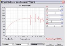
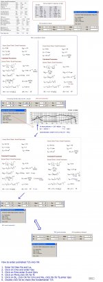
To see the overall system response you need to select the combined response from the tools menu in the SPL window.
")
Attachments
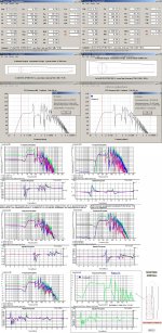
What I am looking at is a quarter wave pipe (TL) with several identical drivers distributed along a portion of the pipe, not for smoothing necessarily but for convenience sake. I realize that HR can not simulate this directly (nor would it be reasonable to rewrite it to handle it) but what I am wondering is if one could not get a close enough approximation of the total response by simulating each position and averaging the results.
You've stuck an idea in my head:
What if Hornresp could crunch the numbers of multiple records? That is to say that if you created a file for each position along the path where a driver is located. It would also be interesting if you could use another mode of the multiple record technique for comparison. I think it would a need a check box to indicate if you wanted to sum or compare them and a row of buttons to load files that would allow you to also pick a color for the graph output...
...You've stuck an idea in my head:
What if Hornresp could crunch the numbers of multiple records? ...
Hi,
Why not DIY.
..There are endless use if taking advantage of HR's export files.Here is an example:
b
Attachments
Hi bjorno,Hi,
Why not DIY.
That's quite the undertaking, but I do wonder if hornresp could do a better job than HOLM? I was thinkning of this as a logical alternative to giving Hornresp a workover to make it aware of multiple driver locations in one record.
I guess that what you are missing is that hornresp initially shows the output from the driver, without the output from the port.
To see the overall system response you need to select the combined response from the tools menu in the SPL window.
Hi Xoc1,
I'm taking about the combined response. It doesn't look like the WinISD's.
For the close box, it's close but not the same, for the BR it's sometimes far away, specially for the low part.
Regards.
I'm taking about the combined response. It doesn't look like the WinISD's. For the close box, it's close but not the same, for the BR it's sometimes far away, specially for the low part.
Hi blo06,
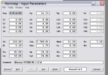
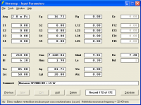
Can you please post a screenprint of your Hornresp input parameters window, and also provide details of the WinISD Driver, Box and Vent values you are using for the purposes of the comparison. Thanks.
Kind regards,
David
Hi blo06,
Can you please post a screenprint of your Hornresp input parameters window, and also provide details of the WinISD Driver, Box and Vent values you are using for the purposes of the comparison. Thanks.
Kind regards,
David
Hi David,
here they are.
Regards.
Attachments
blo06
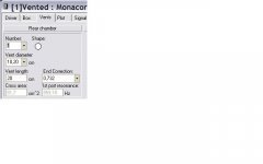
Your AP figure is incorrect.
The AP Parameter is the cross sectional area of the port.
For a 10.2cm diameter round port this would be radius squared X pi = 81.71 sq cm.
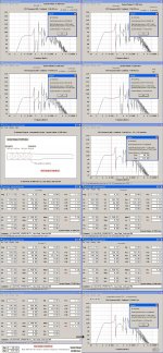
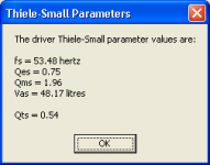
I saw that too but more important is that the T/S parameters are way off.
Reason for this is probably from the advertised Cms value that is not consistent compared to other driver data.
b
Attachments
Last edited:
I saw that too but more important is that the T/S parameters are way off.
Reason for this is probably from the advertised Cms value that is not consistent compared to other driver data.
b
Rectifying a cut and past fault in the picture here above
b
Attachments
here they are.
Hi blo06,
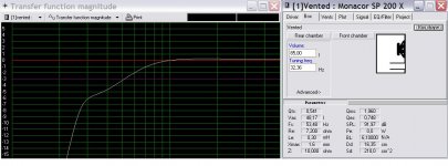
Thanks for the additional information. The following changes are required to the Hornresp input parameter values to make them equivalent to the given WinISD values.
Cms - From 7,70E-01 to 7,66E-04
Rms - From 1,79 to 1,98
Mmd - From 11,50 to 9,81
Ap - From 10,20 to 81,71
With these changes the Hornresp Helmholtz resonance frequency becomes 32,40 hertz compared to the WinISD value of 32,36 hertz.
Kind regards,
David
Attachments
..The following changes are required to the Hornresp input parameter values to make them equivalent to the given WinISD values.
Hi,FYI
No doubt that HR is a good and reliable predictor of ported boxes and IMO surpasses WinISD too but I think the provided T/S is off. See the picture:
b
Attachments
Last edited:
Hi David,
I get a better picture about the numbers. But it's not easy to get the right ones.
I got them from the vendor site
in french but all the same :
Impédance (Z) 8 Ω
Fréquence résonance (fs) 50 Hz
Bande passante maximale f3-15000 Hz
Puissance maximale 70 WMAX
Puissance nominale (P) 35 WRMS
Pression sonore moyenne (1 W/1 m) 92 dB
Compliance susp. (Cms) 0,77 mm/N
Masse mobile (Mms) 11,5 g
Surtension méca. (Qms) 1,96
Surtension élec. (Qes) 0,7
Fact. surtension total (Qts) 0,52
Volume équ. (VAS) 48 l
Résistance DC. (Re) 7,2 Ω
Facteur de force (BxL) 6,1 Tm
Inductance bobine (Le) 0,3 mH
Diamètre bobine 25,5 mm
Support bobine Alu
Excursion linéaire (XMAX) ±1,6 mm
Surface d'émission (Sd) 210 cm2
Poids aimant 17,7 oz.
Poids 1,3 kg
But even with that, it can be tricky to get the good numbers. So I fill the HR boxes with double clicking and answering the questions. This way
CMS = 7,63E-04
MMD = 11,53
BL = 6,55
RMS = 2.13
...
and of course the SPL response looks a bit different than with your numbers... How did you get them ?
So what to do ?
Anyway, I get a better picture of your (+++++) software, and begin to use it with better results.
Thanks for all.
Regards.
Hi,
Another reason for the differences between Hornresp and WinIsd is that Hornresp doesn't take box losses (wall leakage mostly, I think) into account (correct me if I'm wrong, David). These losses are often added in bass reflex models by a Q-factor QL. I think the value used in WinIsd is QL = 7, while in hornresp the equivalent would be to set QL=infinity. The significance of this depends on the Q-values in other parts of the system.
I suspect WinIsd uses the transfer functions given by Small, Thiele, Leach etc. to calculate the response. Hornresp uses a more sophisticated model.
Bjørn
WinISD uses following Q-ValuesI think the value used in WinIsd is QL = 7
An externally hosted image should be here but it was not working when we last tested it.
You can change them by clicking on "Advanced->"
and of course the SPL response looks a bit different than with your numbers... How did you get them ?
Hi blo06,
Using the WinISD driver parameter values you provided I simply generated the unknown electro-mechanical values from the equivalent Thiele-Small parameters using the Hornresp 'Calculate Parameter' tool.
I used the following given values:
Sd = 210,00
Bl = 6,10
Le = 0,30
Re = 7,20
And calculated:
Cms from Sd and Vas.
Mmd from Sd, Cms and fs.
Rms from Cms, fs and Qms.
Kind regards,
David
Another reason for the differences between Hornresp and WinIsd is that Hornresp doesn't take box losses (wall leakage mostly, I think) into account.
Hi Bjørn,
Thanks for pointing this out.
Kind regards,
David
- Home
- Loudspeakers
- Subwoofers
- Hornresp