I don't know it the following topology was already discussed anywhere and if it is useful at all.
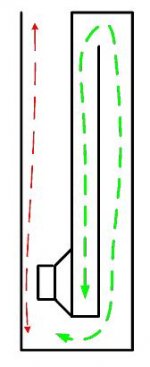
Enclosed you will find a drawing of what I came up with.
The walls do not necessarily have to be parallel of course (i.e. the path may be tapered).
The intended principle is that the red part of the path works as as lambda/4 resonator at the upper cutoff frequency - whereas the green part acts as lambda/2 phase delay at this frequency. At the lower cutoff frequency the whole path length would work as lambda/4 resonator.
I am convinced that it would somehow work the way it is intended to at said frequency extremes - although I am not sure how well. And I am completely unsure how it will act between those frequencies. Maybe there will be not output at all or very peaky or whatever.
Regards
Charles
Attachments
OK I downloaded the program and made a few tries.
Very cool and almost self-explanatory if "classical" horns are to be simulated !
But I can't select the "tapped horn wizard" , i.e. there is no way to get this selection highlighted.
What do I have to watch out for ? I set up a flare with conical sections and no back chamber but I can in no way get the "wizard" highlighted.
Regards
Charles
Those ideas are stolen by the past...
take a look at Arnold Klayman's US patent # 5,177,329 in particular Fig. # 2.
http://www.google.com/patents?id=0ocbAAAAEBAJ&printsec=abstract&zoom=4&dq=klayman,+5177329
take a look at Arnold Klayman's US patent # 5,177,329 in particular Fig. # 2.
http://www.google.com/patents?id=0ocbAAAAEBAJ&printsec=abstract&zoom=4&dq=klayman,+5177329
Re: Those ideas are stolen by the past...
Yes nice, just had a look, its got nothing to do with a horn, i thinks its similar to a ported enclosure, there we resonate the port here to have a huge chamber to resonate instead, will give max 3db gain as ported systems do, i dont think this is an effective or usefull design
am i thinking right ????
moray james said:take a look at Arnold Klayman's US patent # 5,177,329 in
Yes nice, just had a look, its got nothing to do with a horn, i thinks its similar to a ported enclosure, there we resonate the port here to have a huge chamber to resonate instead, will give max 3db gain as ported systems do, i dont think this is an effective or usefull design
am i thinking right ????
Klayman's drawing shows...
duct with straight sides however a taper could also be used. First drawing is a 1/2 wave device with the second using half and 1/4 wave lines. The similarities to a Tap design are obvious. Remember 1/2 wave length is where a horn gets efficient. These designs are said to be very powerful with a number still in use today.
duct with straight sides however a taper could also be used. First drawing is a 1/2 wave device with the second using half and 1/4 wave lines. The similarities to a Tap design are obvious. Remember 1/2 wave length is where a horn gets efficient. These designs are said to be very powerful with a number still in use today.
phase_accurate said:OK I downloaded the program and made a few tries.
Very cool and almost self-explanatory if "classical" horns are to be simulated !
But I can't select the "tapped horn wizard" , i.e. there is no way to get this selection highlighted.
What do I have to watch out for ? I set up a flare with conical sections and no back chamber but I can in no way get the "wizard" highlighted.
Regards
Charles
Neither can I

The program just takes me direct to the calculation results. I' m sure I'm forgetting something, ..but what is it?
Thanks
GM said:Hmm, guess I misunderstood the Q.......... click the EDIT button and now the Tapped Horn Wizard is highlighted. See HELP pg. 9.
Thanks, I fixed it . You MUST specify 3 sections for the tapped horn option to activate. Additionally, while fiddling with parameters, Hornresp accidently datafilled my Vrc to a non - zero value thus disabling the tapped horn option.
Hope this bit of info helps others.
would ber easy enough to...
make a cabinet with the last two feet of panel above the open mouth area exchangable so you could play with tapers or if you choose just leave it solid. Dave (planet 10) is playing with tapers on a BIB in the IBIBK thread below. http://www.diyaudio.com/forums/showthread.php?s=&threadid=95929
make a cabinet with the last two feet of panel above the open mouth area exchangable so you could play with tapers or if you choose just leave it solid. Dave (planet 10) is playing with tapers on a BIB in the IBIBK thread below. http://www.diyaudio.com/forums/showthread.php?s=&threadid=95929
Hi Phase accurate
The configuration you posted would be a Tapped Horn, if it were tapered.
It could have flat response if it were “large enough” and you got all the acoustic and driver parameters right.
I found the “Tapped horn” while exploring the reflected signal within the full range coaxial horns I design for work and thought how can I use that.
The Tapped horn works because the acoustic impedances all (when everything is right) all compensate each other, the dip between the first and second peak on a normal “too small horn” is gone.
Those peaks in a conventional horn reflect the changing load presenter to the cone, they correspond to peaks and dips in the electrical impedance and that governs how much power is delivered vs frequency.
Where the dip would normally be, now both side of the cone radiate fully additively within the horn and that load is present in the impedance as an increase in delivered power.
I don’t know if the link works at work (a new web site sigh, I liked the old one) but there is more of an explanation in the White paper (which also has a “phase accurate” horn too)
Anyway, when everything is right, compared to a conventional horn, for the same size, one can make either a smoother response horn or one with the same sensitivity but lower cutoff, or a combination of both, when the horn is “too small”.
Personally, I think the prior art devices, like the Klayman, Jensen transflex aren’t in use not because of a secret plot to deprive people of bass, but because they all have uncontrolled resonances which sound icky.
Don’t forget, an advantage of a horn is that it has different acoustic impedance at each end, the Tapped horn has a third node which is also variable.
Connected to these is the driver at two of those and radiation resistances driven by the variables set by driver parameters.
What your doing in a sense producing a source which conjugates the load, if that is “near perfect”, you get a nice response and significant sensitivity increase over the driver as a direct radiator and similar increase in maximum output. This can be as much as 10dB or more.
Once the horn is properly large acoustically speaking, the Tapped horn has no advantage however.
Best,
Tom Danley
Danleysoundlabs.com
Hi Tom
I do in no ways doubt that a tapped horn as such works well (you are the master of bass reproduction after all). But the places where I intended to tap the horn seem not to be the best suited ones I have found out after a while.
As a chartered EE I know that in RF one can do transformations and compensations with many kinds of stubs and the like. I was always convinced that this must be feasible with horns also. I am not knowledgeable enough that I had come up with such a thing by myself however.
I am aware of your unity horn design and it's transient properties and I appreciate your attempts for improved transient reproduction in live-sound.
This design would be tempting for a home system as well - its SAF is rather low unfortunately !
Regards
Charles
- Status
- This old topic is closed. If you want to reopen this topic, contact a moderator using the "Report Post" button.
- Home
- Loudspeakers
- Subwoofers
- Another tapped "horn" ?