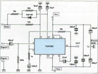
I've edited this schematic taken from a magazine which has taken it from the TDA7294 datasheet and tried to adapt it to TDA7293.
I would simply like to have your feedback about it. I'm not very sure about the bootstrap / bootloader stuff and an some expert's comments about the schematic in general would be more than welcome.
Thank you !
I would simply like to have your feedback about it. I'm not very sure about the bootstrap / bootloader stuff and an some expert's comments about the schematic in general would be more than welcome.
Thank you !
Attachments
First.Elkaid said:I've edited this schematic taken from a magazine which has taken it from the TDA7294 datasheet and tried to adapt it to TDA7293.
Thank you !
Here is download of TDA7293 datasheet TDA7293 PDF Datasheet
TDA7293 is almost the same IC as TDA7294 or TDA7294S
So I guess the circuits are about the same too.
Here is RECOMMENDED application
You always get less problems when staying with recommended circuit.
It is when you start tweak and think you can
make it 10 times better, than the professional people
you can get into some little troubles.
Like burning a couple of ICs and stuff!
Do not underestimate those who write the Datasheet for these
BIG companies. They are certainly no dumb-heads!
I would not say it is impossible to improve
with some few % percent or promille.
Or something like that

I recommend you to download TDA7293 datasheet - It is already hard to find on the Webb -
Read all of it. How you can modify component values ...
Do not take the SHORTCUT:
staying WITHOUT KNOWLEDGE about the Component you are going to use.
Here is recommended normal application for TDA7293:
Attachments
Some projects Using TDA7293 and 7294
Some projects Using TDA7293 and 7294
Endstufen - UB Elektronik
Ultich Böhmke Elektronik
----------------------------------
Endstufe 100
Datenblatt für Rev. 1.10 (789KB) Platine wird nicht mehr ausgeliefert!
Datenblatt für Rev. 1.11 (1,5MB) neueste Auflage
DMOS-Endstufe 100 W (bis 300 W durch Brücke/Parallelschaltung) mit TDA 7293. Gute Meßwerte und Super-Klang. Sehr kompakter Aufbau für vielseitige Anwendung, insbesondere BiAmping und Aktivlautsprecher.
------------------------------
Output Endstage 100
100W (300W bridged/parallel) with TDA7293
for you who doesn't know Deutsch (halojoy does!)
He also have some "VorVerstärker" PreAmplifiers.
Hier ist das Bild von "Endstufe 100"
Here is the image of "EndStage 100"
Attachments
I have had problems with the TDA7293 in configuration mainly and slave. 
With a power supply of +/- 49v without audio signal, to obtain 100 W. The bank of electrolitics is of 30000uf for rail.
I did equally to the of ST's application note, and when it works, the specifications of the manufacturer are fulfilled, but often when I put it in on the IC slave burns.

Does someone know because this happens?
With a power supply of +/- 49v without audio signal, to obtain 100 W. The bank of electrolitics is of 30000uf for rail.
I did equally to the of ST's application note, and when it works, the specifications of the manufacturer are fulfilled, but often when I put it in on the IC slave burns.
Does someone know because this happens?
sixtek said:Hey,
+/-49V and 30.000uF/rail?!
That's too much!
Use +/-40V rails with max. 10.000uF PSU capacitors.
But at the time are they lies ST's specifications?

They say that the IC supports +/-60v without signal.
With +/-40v I do not obtain 100W
There is a difference between the ST application notes, I am going to try with it (the inputs of the IC slave now are connected to -V and before to mass)
Bye.
" ... With +/-40v I do not obtain 100W " ... And you don't get quite the high 10% distortion at full power, either.
sixtek: " ... Use +/-40V rails with max. 10.000uF PSU capacitors. ..." ... but don't forget those snubbing caps ... the factory suggested sckemo suggests as little as 1000 uF per rail, but note those 100 nF snubbing caps (0.1 uF) ... be sure they are the plastic / MKT / polystyrene type =
" ... And you don't get quite the high 10% distortion at full power, either. sixtek: " ... Use +/-40V rails with max. 10.000uF PSU capacitors. ..." ... but don't forget those snubbing caps ... the factory suggested sckemo suggests as little as 1000 uF per rail, but note those 100 nF snubbing caps (0.1 uF) ... be sure they are the plastic / MKT / polystyrene type =
I have a couple of Velleman PSU modules for use in low profile rack mount chassis and they have (10,000 uF X 2) = 20,000 uF per rail, as you say ... quite inexpensive as I recall and they have the diode bridge plus LED power indicators ... ... a nice fit for the TDA7293 ... there is also some solder points for the 100nF plastic snubbing caps, but I would put them closer to the chip amp, rather than on the PSU module ...
Oops! these particular Velleman PSU filter modules should not be used with more than +/- 40 VDC rails as the caps have an absolute max rating of 50 VDC ...
... a nice fit for the TDA7293 ... there is also some solder points for the 100nF plastic snubbing caps, but I would put them closer to the chip amp, rather than on the PSU module ...Oops! these particular Velleman PSU filter modules should not be used with more than +/- 40 VDC rails as the caps have an absolute max rating of 50 VDC ...
Sorry, it is true that the letters are a bit big, and the color calls the attention, but only I want to alert all in order that they do not lose time and efforts. I do not try to shout, because of it not write in capital letter.
I tried to communicate with ST sending the questions and never receipt answer.
If someone used the AN of ST's with the TDA7293 in parallel and obtained 100W, please that says to me since it did.
Thank you.
I tried to communicate with ST sending the questions and never receipt answer.
If someone used the AN of ST's with the TDA7293 in parallel and obtained 100W, please that says to me since it did.
Thank you.
Great. At least you acknowledge that the post wasn't really appropriate.
Coming to the chip. Maybe some interesting experiments could still be done. Note the separation of the input stage supply from the output stage supply . You could have a very clean supply for the input stage and help the amp sonically . The catch however is that the supply voltage for the input stage must not vary more than 0.6 V ( I think ) from the output stage supply voltage. If it does , then the chip will self destruct ! (That I'm sure is not the correct condition ).
Read the app note. This has been described there. Some forum members have discussed this in detail I think. Search for TDA7294 or TDA7293 on this forum and you will find it.
For separated supplies there was a diode link that maintained the condition that prevented breakdown.
Most semiconductors handle a bit more voltage than specified and so I think this chip might handle more voltage though I'm not sure about the power rating . You 'must' read the app note carefully . In any case between 100 watts and 80 watts there is only a 0.97db difference. That will be hardly audible.
Some people like this chip. I have a pair and will be trying it out sometime.
Cheers.
TDA 7293
Marshall guitar amplifiers are using this chip in parallel with success in their 100W amplifiers. I've repaired several of them in the past. When I get home tonight I'll dig out what model and post a schematic. They use a couple 12AX7s up front and the power amp is dual 7293's. Wait I remember, it was Valvestates.
AVT 150 was the model.
TDA 7293
The model was right AVT-150 or AVT 275, but they are not called valvestates (sorry) I got these schematics fom Dr. Tube. (Very nice man.) The amp has two poweramp boards each sporting a TDA7293. One schematic is the power amp board (62-02). The other shows how they are connected in parallel on page 4 (61-02). I was surprised to see these in a guitar amp. Anyway, you should be able to figure out the whole parallel thing from this. good luck and let me know if this helped.
The model was right AVT-150 or AVT 275, but they are not called valvestates (sorry) I got these schematics fom Dr. Tube. (Very nice man.) The amp has two poweramp boards each sporting a TDA7293. One schematic is the power amp board (62-02). The other shows how they are connected in parallel on page 4 (61-02). I was surprised to see these in a guitar amp. Anyway, you should be able to figure out the whole parallel thing from this. good luck and let me know if this helped.
Attachments
ashok said:Note the separation of the input stage supply from the output stage supply . You could have a very clean supply for the input stage and help the amp sonically . The catch however is that the supply voltage for the input stage must not vary more than 0.6 V ( I think ) from the output stage supply voltage. If it does , then the chip will self destruct ! (That I'm sure is not the correct condition ).
Read the app note. This has been described there. Some forum members have discussed this in detail I think. Search for TDA7294 or TDA7293 on this forum and you will find it.
The input stage can have separate power, and it is strongly suggested that it be higher than taht for the output stage. HOWEVER! Because the V- pin of the input stage is tied to the chip substrate, care should be taken in power supply sequencing. The substrate must ALWAYS be the most negative point of the chip, or the chip will latch-up and burn. This is easily ensured by a diode from input stage V- to output stage V-, which pulls input stage V- always within 0.5V or so positive with respect to output stage V-, and this is as high as it may go. It should be equal or lower in normal operation.
In the same manner, parallel TDA7293 must NEVER be powered from different power supplies, and the connecting line must be as short as possible. The input signal to the slave must never appear before the power supply.
Regarding the V+ of the input stage, it is also shared by the driver stage. If it is sufficiently higher than the V+ of the output stage, there is no need to use the bootstrap or boot-loader caps any more. However, this will mean a slight loss of maximum obtainable power because the output stage V+ will have to be about 42V or less, with the input stage V+ at 50V. This is already actually beyond absolutely safe spec, care should be taken on power sequencing. It is unfortunately not obvious how much higher the input stage V+ can be with respect to the output stage V+, the only clue being the 'class G' implementation example (which I suggest potential users of this chip to study carefully), where it is about 20V. So far I have found that about 8V is always enough to get output stage swing near the output V+ rail, so it stands to reason more is not necessary. Even so, my implementations have a zener clamp that keeps input stage V+ at most 15V higher, should the output stage V+ fail or droop too much.
Writing pompous red posts about ST being liars is really bad form. Instead i suggest careful reading of the specs for maximum voltage differentials between inputs and power lines. Friom there it becomes clear that for absolute safety (unless you want to add a lot of protection for various pins) output stage V- and V+ should not be over +-45V under any circumstances. If youw ant to use the full +-60V unloaded, you ahve to be very careful as to how you handle the signal and control inputs during power up and power down.
Secondly, +-43V is enough for 100W into 8 ohms on a properly implemented circuit, because the TDA7293 can have an output swing practically rail to rail. It also pays to read the FULL spec on output power, and this is 100W at 10% THD into 8 ohms from a +-40V supply. 10% THD means it is already clipping so RMS voltages and currentsa re not 0.707... times peak any more. manufacturers are alowed to spec their chip as they wish, users who do not read the spec correctly and instead rely on wishful thinking, get what they deserve.
Full power output on a TDA7293 is possible but only under controlled circumstances because of the chip's relatively limited power dissipation (again, read the application notes!). I have built several amps with the 7294 and 7293, most with separate regulated input stage rails, some with even more unorthodox refinements. So far I have found the chip to be completely reliable, as long as you read the specs and produce a conservative design that will satisfy them under all circumstances. I have found that the TDA7294 will work onit's own with even difficult loads implemented as an amp of up to 40-50 honest conservative Watts of power (which usually means about 70-80 peak), the 7293 is only slightly better because of the same limited dissipation, but has more versatility which comes in on other fronts.
With regulated front end, the sound is actually very very good - slightly laid back, though, and the amp is virtually noiseless.
TDA7293 vs TDA7294
For some clarification in the subject:
TDA7293 is newer than 7294 and more robust, especified for 120V no signal and 100V operation, while 7294 is especified for 100V no signal and 80V operation.
Some others very important differences:
- Only TDA7293 is allowed to have the output stage paralelled.
- Only TDA7293 have clipping/overload indicator output.
- Only TDA7293 have choices of "bootstrap" or "bootloader"
Ratings for maximum operating and non-operating voltage are for 8 (eight) ohms and is an indicator for the mass-market audio enginner about safety margins, allowing the final product to be used in regions with too much AC variations and to get a maximum peak musical power with a poorly regulated transformer (read: thrifty...)
Ilimzn: thank you very much for your considerations about use of separated front end supply. javascript:smilie('')
I have had this idea when first saw the datasheet but i'm not tried yet. at first glance, this possibility appeared very good to be true...
Marcos
For some clarification in the subject:
TDA7293 is newer than 7294 and more robust, especified for 120V no signal and 100V operation, while 7294 is especified for 100V no signal and 80V operation.
Some others very important differences:
- Only TDA7293 is allowed to have the output stage paralelled.
- Only TDA7293 have clipping/overload indicator output.
- Only TDA7293 have choices of "bootstrap" or "bootloader"
Ratings for maximum operating and non-operating voltage are for 8 (eight) ohms and is an indicator for the mass-market audio enginner about safety margins, allowing the final product to be used in regions with too much AC variations and to get a maximum peak musical power with a poorly regulated transformer (read: thrifty...)
Ilimzn: thank you very much for your considerations about use of separated front end supply. javascript:smilie('
')I have had this idea when first saw the datasheet but i'm not tried yet. at first glance, this possibility appeared very good to be true...
Marcos
- Status
- This old topic is closed. If you want to reopen this topic, contact a moderator using the "Report Post" button.
- Home
- Amplifiers
- Solid State
- Need help on this TDA7293 schematic