If the stage preceding output mosfets is single-ended VAS, than it cannot source more than 10mA, that's low for driving mosfets.
But it should be workable, contrary to bipolar output mosfets do not require any DC current to work, with 10mA expect some rise in THD with frequency and limited slew rate.
Adam
But it should be workable, contrary to bipolar output mosfets do not require any DC current to work, with 10mA expect some rise in THD with frequency and limited slew rate.
Adam
Hi Max,
what is the capacitance of the IRF130?
The driver has to charge those three capacitances.
At high audio frequencies this is a surprisingly large current.
10mA might be too little.
If it were a follower, then it goes into ClassAB, but dissipation at high frequencies becomes the problem, particularly during testing.
Hi Max,
you might find this spreadsheet useful or confusing.
Look at 2n2F and 20kHz for loading in the audio band for your 3pair from a 10mA VAS.
Now look at 2n2F & 100kHz. How low does the Vpk need to be to keep the Ipk below 10mA?
A classA stage does not drive a capacitance particularly well at high frequency.
The problem you will have is deciding what capacitance the FETs present to the VAS.
There seem to be many conflicting views.
Then deciding what Vpeak is sent to the FETs when testing and when listening to ordinary/extra-ordinary music/sound effects.
You can avoid the dilema by using a lower VAS current and inserting a follower that goes into classAB when the current demand inadvertently goes too high. At least it will sound better than when clipping. But does the follower sound better on ordinary signals?
Attachments
")
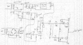
Hi Andrew,
my schematic is the Buzquito of Jean-Marc Plantefève ( http://perso.orange.fr/jm.plantefeve/sche.html ) Thank You! Maxpou
my schematic is the Buzquito of Jean-Marc Plantefève ( http://perso.orange.fr/jm.plantefeve/sche.html ) Thank You! Maxpou
why? Heat man.. heat..
hmm i use irfp240 ,9140 but with heat correction, works awesome yes..
and also bear in mind that the capacitance it works in is connected as source follower, not exactly the same as if source would be connected to earth but yes still one might want to have more than 10mA, that seems small
hmm i use irfp240 ,9140 but with heat correction, works awesome yes..
and also bear in mind that the capacitance it works in is connected as source follower, not exactly the same as if source would be connected to earth but yes still one might want to have more than 10mA, that seems small
nikwal said:why? Heat man.. heat..
hmm i use irfp240 ,9140 but with heat correction, works awesome yes..
and also bear in mind that the capacitance it works in is connected as source follower, not exactly the same as if source would be connected to earth but yes still one might want to have more than 10mA, that seems small
I support this statement.
Think of it from a different angle: when we design a tube kathode follower, we can have a coupling cap of say 10 nF and still more than 100 kHz, if the grid resistor is connected to the kathoide. This give a kind of 'positive feedback', any way, the grid resistance is multiplied - and the grid capacitance to the cathode is annihilated or neutralized if you like to use that word.
So in that sense, driving the IRF130 from a 20 mA drive current does not give a slew rate for normal audio frequencies under normal loads (say less than 10 volt drive output and less that 1,5 Amp). I have a IRF 130 SE output (drives into a constant current) and my LS is a Quad. Still this works fine.
Some have found a too high idle current in the drive to harden the sound (too much dynamics?).
regards
albert
Dear DJK,
I am interested in your comments: why should something be changed?
Thermal runaway must be the issue.
You might refer to the difference between the famous Toshiba 2sk134/2sj49, 2sk135/2sj50, 2SK175/2SJ55, 2SK176/2SJ56 pairs with a negative temperature coefficient to any IRF pair where the thermal feedback is 'positive'.
But when I made my prototype with the IRF130, running almost 2 amp at 20 volt into a current sink I was really scared. But then - I noted almost no thermal drift (<100 mV) from start till after the temperature was stable (50-60 degrees) with a 0,33 ohm source ressitance. So my conclusion is that the idle current did not run away too much.
In a second prototype I used the 2SJ50 as P-Fet, and again there was no effect, less even. Maybe the two curves compensated.
However, with a N/P FET pair without source resistance, the bias must be set low and consequently it will take a time to set to a thermal equilibrium.
In the following table I calculated the effect of the source resistor on the current drift (the table has the junction tem 25deg and 175 deg) based on the Intersil docs. I did not take the increase of the internal resistance into account.
As the internal drain to source resistance easily goes from 1 ohm to 2 ohms when the junction rises from 25deg to 175 deg, this effect in practice could be lower still. But I'm not an EE, just a bricoleur.
So a SIMPLE design should have a source resistance in it and the fixed bias should be set when hot.
A complex design should have a current feedback on one gate, using an opamp or maybe even a DC clamp made on one source resistor (like 0,33 ohm) to force the current to 2 Amp with a transistor. The latter I have not tried but many transistor amps have something like that. I have implemented the opamp version like so many have done. This will immediately give 2 amp, and slowly the bias is lowered.
As regards Maxpou's original question, note that in L'Audiophile, oct 1991, Mr Nassérian designed a cathode follower with double ECC88 to drive up to five 2sk135/2sj50 parallel output sets. These even have similar capacitance as the IRF130. That driver stage runs at some 20 ma. And interestingly the stage uses no coupling capacitor.
I am interested in your comments: why should something be changed?
Thermal runaway must be the issue.
You might refer to the difference between the famous Toshiba 2sk134/2sj49, 2sk135/2sj50, 2SK175/2SJ55, 2SK176/2SJ56 pairs with a negative temperature coefficient to any IRF pair where the thermal feedback is 'positive'.
But when I made my prototype with the IRF130, running almost 2 amp at 20 volt into a current sink I was really scared.
But then - I noted almost no thermal drift (<100 mV) from start till after the temperature was stable (50-60 degrees) with a 0,33 ohm source ressitance. So my conclusion is that the idle current did not run away too much. In a second prototype I used the 2SJ50 as P-Fet, and again there was no effect, less even. Maybe the two curves compensated.
However, with a N/P FET pair without source resistance, the bias must be set low and consequently it will take a time to set to a thermal equilibrium.
In the following table I calculated the effect of the source resistor on the current drift (the table has the junction tem 25deg and 175 deg) based on the Intersil docs. I did not take the increase of the internal resistance into account.
As the internal drain to source resistance easily goes from 1 ohm to 2 ohms when the junction rises from 25deg to 175 deg, this effect in practice could be lower still. But I'm not an EE, just a bricoleur.
So a SIMPLE design should have a source resistance in it and the fixed bias should be set when hot.
A complex design should have a current feedback on one gate, using an opamp or maybe even a DC clamp made on one source resistor (like 0,33 ohm) to force the current to 2 Amp with a transistor. The latter I have not tried but many transistor amps have something like that. I have implemented the opamp version like so many have done. This will immediately give 2 amp, and slowly the bias is lowered.
As regards Maxpou's original question, note that in L'Audiophile, oct 1991, Mr Nassérian designed a cathode follower with double ECC88 to drive up to five 2sk135/2sj50 parallel output sets. These even have similar capacitance as the IRF130. That driver stage runs at some 20 ma. And interestingly the stage uses no coupling capacitor.
Attachments
- Status
- This old topic is closed. If you want to reopen this topic, contact a moderator using the "Report Post" button.
- Home
- Amplifiers
- Solid State
- IRF130, 9130 drive?