I need some info regarding replacing the output transistors. I realize finding original replacements is not going to happen. I have purchased a pair of IRFP9240 and IRFP240 after reading some threads about this amp.
I need to know if I need to modify anything else inside to get these to work. Also should I replace both channels with the new parts. I believe that one channels original outputs are still working. So do I need to replace both sides?
I did try and install these new parts on the dead channel. Everthing went OK I thought. But as I turned it on and try to adjust the Bias I am getting 0.0v on one side and the other seems fine I can set it to the 65 mv the service manual asks for.
I have done many tests to see where I am getting voltage. Or for short resistors. I found a couple that were out of tolerance and replaed them accordingly. Voltage is making it to the main board. On the side with the original outputs. My measurements are not to far off the required values. The other side gets voltage but nothing across the emitter resistors. I cannot find the short. Please help
I am not looking to send this out to be fixed by a tech. I want to do it myself. I do have some knowlege in electronics but I am not a tech or professional. Please anyone that can help me I greatly appreciate it.
Do I need to look at the driver board? Or main board? or other mods to get these outputs to work.
The amp's tubes both light up. I really like this amp. Please reply.
Possible replacements fro 2SK405/2SJ115
Hi rinsbag,
Since nobody replied, here is my (limited) knowledge of the issue:
1) I have bought an LV-105u recently, left output stage is burned out. I haven't had much time to look into it and repair the damage.
2) The Luxman LV-105u is a great amp, however the output stage MOSFET transistors are known to burn quite easily if driven too hard. IMHO they are operated too near their SOA.
3) Original transistors are 2SK405/2SJ115, which can be found but you really have to look hard on the net.
4) AFAIK nearest replacements are 2SK1529/2SJ200, and 2SK1530/2SJ201.
5) I have read about people using 2SK1058/2SJ162.
6) AFAIK IRFP9240 and IRFP240 are not really recommended.
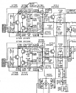
Here is an extract from the schematics showing the output stage.
I am preparing a small quantity order for 2SK1529/2SJ200 devices, if you need two pairs or more just PM me.
Hi rinsbag,
Since nobody replied, here is my (limited) knowledge of the issue:
1) I have bought an LV-105u recently, left output stage is burned out. I haven't had much time to look into it and repair the damage.
2) The Luxman LV-105u is a great amp, however the output stage MOSFET transistors are known to burn quite easily if driven too hard. IMHO they are operated too near their SOA.
3) Original transistors are 2SK405/2SJ115, which can be found but you really have to look hard on the net.
4) AFAIK nearest replacements are 2SK1529/2SJ200, and 2SK1530/2SJ201.
5) I have read about people using 2SK1058/2SJ162.
6) AFAIK IRFP9240 and IRFP240 are not really recommended.
Here is an extract from the schematics showing the output stage.
I am preparing a small quantity order for 2SK1529/2SJ200 devices, if you need two pairs or more just PM me.
Attachments
about using IFRP9240 and 240
Hey Sorry its been a while since I was working on this amp. But seeing it just sitting there sucks. I now know a bit more about this but still could use some assistance.
Gigapod. Is there any thing you can tell me about using the formentioned? I have been testing for the correct voltages and some seem really close to the specs in the schematic. How close do they have to be?
Please reply. anybody. Is it a power supply thing?
IRFP swap.
Hi guys !
I've given a few thoughts on this matter, these are my suggestions:
- the original output devices are similar to standard hexfets.
- the most important difference is the amount of gate voltage needed
to "open" the device, also called as Vgs(th) or Vgs(off).
- 2sk405/2sj115 Vgs(th)= 0.8V to 2.8V
- IRFP240/9240 Vgs(th)= 2V to 4V
- pinout is the same.
- just drop in the IRFP's and try to adjust the quiescent current to nominal value (100 mA ?)
- if you cannot set the needed amount, try to replace R7301/7302 with
4.7kOhm resistor, this will extend the range of Vgs setting.
I hope you dont fry anything !
Good luck !
K1529 and J200 can be used as replacements with no further modification. K1530 and J201 will also work fine and offer even better robustness. Although the input capacitance of these parts is somewhat higher, the higher gm makes them about the same to drive as the originals. I have tried both these options and given the higher Idmax of the K1530/J201, would use them as the preferred option.
From the IRF cam, the ideal pair to use would be an IRFP340 and IRFP9240, but an IRFP240 will work as well. The bias generator will have to be modified due to (much) higher treshold voltages. Unlike the K/J parts, with a treshold between 1 and 1.5V, the IRFP parts will be closer to 4V each for the 100mA standing current. The original trimmer will not have enough range. R7301/7302 have to be replaced by higher values, try 5.6k.
I have not tried the K1058/J162 combo, and would not do it based on the lower maximum ID of these parts. This might work in the smaller LV103, though. The problem here is that the pinout is different, the source resistors have to be removed and the bias arrangement modified to a single series pot (all other parts must be removed/shorted as necessary).
First hand repair results
OK
I have taken action on this one. Late last night or early morning this day I had success")
I choosed Ilimzn suggestions on Fet's. IRFP340/IRFP9240. They are easy to get, and fairly cheap from my normal supplyers. The mentioned SK and SJ parts are harder to come by. It looks You have to buy them from E-bay.
I changed the R7302 resistor in the bias circuit on the right channel, where I did this job. Lord Winter's suggestion, 4.7k ohm, was right on spot. My Fet's opened between 3.4V and -3.05V respectively.
There was some burned resitors around the old Fet's Current sensor circuit and also the 0.22 ohm R7318 resistor was broken. Checked power on the Driver board and also checked the driver boards last tranny, the buffer after the tube Q7110, and then I tried.... Easy on the variac, lowest Bias ..... poff, both Fet's shorted on all legs I didn't had a chance to measure or understand what happend. After another round, measuring resistors, unsolder and measuring transistors around the endstage I found one broken gate resistor. The 100 ohm R7308. Next time around I had my success Those gate resistors are very important.
I will listen some more today and maybe measure eventual difference between the two different endstages. I will probably change the old stage as well, so that they become the same. But for the moment I will relax and just listen to this fine amplifier. It's silent when it should and the sound is very good.
I have a very low hiss on left channel which sound as a thermionic tube phenomenon. It comes and goes. I may have to buy new tubes later on.
Anyhow this comment is for you all wondering if it's possible to use something else then the original Fet's. I have done it and it works very well so far .
.
And also, you do not need to change every transistor on the driver board or anywhere else. You just need to change the faulty parts.
And another thing. Change the large electrolyth after the filament rectifier for the tubes. It's probably dry and has no uF value at all, as in the state my cap was.
OK
I have taken action on this one. Late last night or early morning this day I had success
I choosed Ilimzn suggestions on Fet's. IRFP340/IRFP9240. They are easy to get, and fairly cheap from my normal supplyers. The mentioned SK and SJ parts are harder to come by. It looks You have to buy them from E-bay.
I changed the R7302 resistor in the bias circuit on the right channel, where I did this job. Lord Winter's suggestion, 4.7k ohm, was right on spot.
My Fet's opened between 3.4V and -3.05V respectively.There was some burned resitors around the old Fet's Current sensor circuit and also the 0.22 ohm R7318 resistor was broken. Checked power on the Driver board and also checked the driver boards last tranny, the buffer after the tube Q7110, and then I tried.... Easy on the variac, lowest Bias ..... poff, both Fet's shorted on all legs
I didn't had a chance to measure or understand what happend. After another round, measuring resistors, unsolder and measuring transistors around the endstage I found one broken gate resistor. The 100 ohm R7308. Next time around I had my success Those gate resistors are very important.I will listen some more today and maybe measure eventual difference between the two different endstages. I will probably change the old stage as well, so that they become the same. But for the moment I will relax and just listen to this fine amplifier. It's silent when it should and the sound is very good.
I have a very low hiss on left channel which sound as a thermionic tube phenomenon. It comes and goes. I may have to buy new tubes later on.
Anyhow this comment is for you all wondering if it's possible to use something else then the original Fet's. I have done it and it works very well so far
.And also, you do not need to change every transistor on the driver board or anywhere else. You just need to change the faulty parts.
And another thing. Change the large electrolyth after the filament rectifier for the tubes. It's probably dry and has no uF value at all, as in the state my cap was.
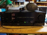
After cleaning behind the upper faceplate and where the Tube glows.
After two days of running and checking contacts and tubes this baby now works perfekt. No hiss and hum, just music. The tubes measures excellent and even on the tubetester AVO MKIII.
Anyone else up and running this amp with satisfaction?
After two days of running and checking contacts and tubes this baby now works perfekt. No hiss and hum, just music. The tubes measures excellent and even on the tubetester AVO MKIII.
Anyone else up and running this amp with satisfaction?
Attachments
Do the output fets need matching on this amp (the lv-105)?
No.
Ok,
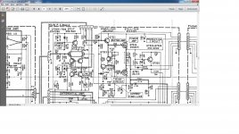
So I have replaced the outputs on this amp (luxman lv-105) with irfp340/9240, all was going well until I tried to set the bias, which didn't move from 0v, now I know with the 105u you can change a resistor to give the bias pot more range, I assume the same with the original 105, would this resistor be 7323 on the schematic below.
So I have replaced the outputs on this amp (luxman lv-105) with irfp340/9240, all was going well until I tried to set the bias, which didn't move from 0v, now I know with the 105u you can change a resistor to give the bias pot more range, I assume the same with the original 105, would this resistor be 7323 on the schematic below.
Attachments
Thanks Mooly,
Just tried this with 4.7k resistors and have found that it lets me adjust from 0v to ~50mv
on one channel but only 0v to 10mv on the other, raising the resistor on this channel to 6.8k lets me adjust to circa 50mv, could it be normal to have an imbalance like this?
What would be the nominal value to adjust to? would it be 45mv as stated in the manual for the original outputs or 100mv as suggested in other posts?
Well I would have thought around 150 milliamps give or take which would be 33 millivolts across either 0.22 ohm (no speakers connected because DC offset affects the result). Yes its normal for there to be a difference, that's partly why we need a pot in the place.
The originals... are they Lateral FET's ? The pin outs suggest not but I'm not sure. A lot of references refer to these as laterals. Is Q7313 mounted on the main heatsink to sense the temperature of the outputs ? If it is not then you might have a problem with thermal stability and possible thermal runaway.
The originals... are they Lateral FET's ? The pin outs suggest not but I'm not sure. A lot of references refer to these as laterals. Is Q7313 mounted on the main heatsink to sense the temperature of the outputs ? If it is not then you might have a problem with thermal stability and possible thermal runaway.
- Status
- This old topic is closed. If you want to reopen this topic, contact a moderator using the "Report Post" button.
- Home
- Amplifiers
- Solid State
- Luxman LV-105u replacing outputs help!