bogdan_borko said:MINI CLASS A?
good joke !
Well at 12W rms into 4 ohms, it isn't the Morris Major of class A amplifiers, isn't it?
G.Kleinschmidt said:Finally.....just finished the amplifier PCB. There have been a few minor changes to the circuit. I'll update it over the next couple of days. Now I have to go and eat dinner.
Bye bye.
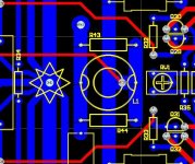
Wow that is really a STAR Ground !
Do you also isolate the input/feedback circuit ground from the high power ground?
fab said:
Wow that is really a STAR Ground !
Do you also isolate the input/feedback circuit ground from the high power ground?
Now even more starry
 (I got a little artistic while tidying up the component overlay – se attached picture). I also moved the NFB pick-off point to a more optimal position. That pretty much finishes it all off. Now I can move on to the regulator board
There is a separate ‘small signal’ ground on the amplifier PCB, isolated from the main power ground by R1. This isolated ‘small signal’ ground also connects to the GND terminal of the input RCA socket, which is isolated from both the amplifier chassis and the ‘small signal’ ground of the other channel.
Cheers,
Glen
Attachments
m_buzzi said:Hi,
Since I'm trying many vas stages I would like to see, if possible, the final schematic of your amp which seems to be available no more.
Could you link it here or mail me at michele.buzzi@[nospam]gmail.com? (cut off the [no spam])
Thanks,
Michele
Sorry that I don't have my webpage up anymore. I'll try to get the schematic out by the end of the week - the computer it is on / study stuff is currently upside down due to home renovations.
Cheers,
Glen
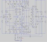
OK, I don't have access to the original schmatics ATM, but I just redrew the cct from memory in LTspice (had a little free time).
The schematic is a bit crappy (resolution / file size constraints) but it is readable.
THD-20kHz sims as follows:
1W / 4 ohm
0.000053%
12W / 4 ohm
0.000946%
OPS bias current is 1.5A
I have built a prototype unit and confirmed the ~10ppm THD-20.
The schematic is a bit crappy (resolution / file size constraints) but it is readable.
THD-20kHz sims as follows:
1W / 4 ohm
0.000053%
12W / 4 ohm
0.000946%
OPS bias current is 1.5A
I have built a prototype unit and confirmed the ~10ppm THD-20.
Attachments
atiq19 said:I wonder why there are few serious designs in low power level.
Same here
Hi Atiq.
I never sold or had a batch of boards made for this amp. I've only ever done that for the K10A amp.
I etched my own boards for this one. I'm part way through writing up a webpage for this amp to add to my website which will have all the details. I am very busy with work and other things at the moment, so it's taking me a while.
Cheers,
Glen
OK, I've put up what I've written so far:
http://users.picknowl.com.au/~glenk/K12A.HTM
Full schematic diagram for the amp module included.
Cheers,
Glen
http://users.picknowl.com.au/~glenk/K12A.HTM
Full schematic diagram for the amp module included.
Cheers,
Glen
ostripper said:Well written article and schema..
purpose of D2 - D3 in schema??
OS
They are voltage clamps at the VAS bases which limit the maximum VAS current to ~20mA.
This keeps things under control when the amplifier clips.
Cheers,
Glen
Thank you, I thought they might be ...more simple
than cordells solution as well.
As we use the same cascoded VAS , looks like a cool upgrade.
just 2 more zeners/diodes.
Would you have to change D4/5 - D6/7 for a non-EF'ed
VAS as well?? How does it work? does it clamp input of VAS before
Q24/27 go into saturation??
When it works, does it eliminate "sticking"??
OS
ostripper said:Thank you, I thought they might be ...more simple
than cordells solution as well.
As we use the same cascoded VAS , looks like a cool upgrade.
just 2 more zeners/diodes.
Would you have to change D4/5 - D6/7 for a non-EF'ed
VAS as well?? How does it work? does it clamp input of VAS before
Q24/27 go into saturation??
When it works, does it eliminate "sticking"??
OS
It eliminates one cause of sticking which is addressed in the rather different Cordell amp by the reverse-parallel diodes connected across the differential output of the LTP.
Q24 and Q27 are prevented from saturating. The cascode transistors cannot saturate either as their collector voltage is limited by the lower voltage rails provided for the triple EF output stage.
There is only one unaddressed source of sticking in this amp – the pre-drivers of the triple EF are allowed to saturate. The pre-drivers are fast small signal devices and recover quickly, however. Sticking time is about 1uS and can be seen here (post 2550):
http://www.diyaudio.com/forums/showthread.php?postid=1707755#post1707755
This sticking could be eliminated with the addition of a voltage clamp at the VAS output, but I decided against this, as I wanted the greatest output swing possible from the low power output stage. 1uS sticking is a pretty minor issue.
Cheers,
Glen
- Status
- This old topic is closed. If you want to reopen this topic, contact a moderator using the "Report Post" button.
- Home
- Amplifiers
- Solid State
- My new mini Class A amp.