I am scheming up a discreet FET preamp for portable use that will be powered from a rechargable Li-ion flat pack battery, run through a monolithic switching voltage quadrupler to give me some more headroom, and then a small pi filter into a simple 3 terminal regulator to smooth out the switching ripple.
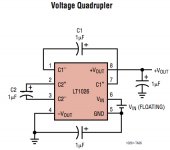
I tried a few diffferent schemed to get the lowest parts-count on the switching circuit, and ended up setling on the quadrupler scheme in the LT1026 data sheet. The DC battery supply is floating, and the output of the quadrupler will be positive single polarity, so would the best grounding scheme for the signal portion (fet, input/output jacks etc) of the circuit to minimize switching "junk" from contaminating the signal be to either:
A) reference the signal grounds to a star point on the chassis where pin 4 of the regulator is grounded?
B) Reference the signal grounds to the pin 5 virtual floating 'ground' of the negative battery terminal?
C) Use a different voltage multiplier scheme
Attachments
You haven't shown the preamp circuit. Does it require a split (+/-/gnd) power supply? If it only requires a single supply, its ground should be the same as the power supply ground (not the battery terminal).
Also, you won't get much current from this power supply. I can't seem to get to the Linear Tech website to check it, but I wouldn't expect more than maybe 10 mA. How much power does your preamp circuit require? If it's discrete, probably more than this.
Also, you won't get much current from this power supply. I can't seem to get to the Linear Tech website to check it, but I wouldn't expect more than maybe 10 mA. How much power does your preamp circuit require? If it's discrete, probably more than this.
The cleanest scheme will be the one where you get no ripple component flowing in a 0v line shared with the preamp's current return. IOW, arrange your PSU (battery/switcher/pi filter/reg) so that the 0v link between PSU and preamp is connects as close as possible to the ov end output cap on that final reg. What happens then on the PSU side matters a lot less.
Theres no reason in principle why you shouldnt use a switcher to boost the battery output, but for keeping switching gunk out of the final 'PSU' output that PI filter could be critical. 3-pin regs are very little help at HF - here's a simple test I did a while ago...:
http://www.acoustica.org.uk/t/3pin_reg_notes2.html
paulb said:You haven't shown the preamp circuit. Does it require a split (+/-/gnd) power supply? If it only requires a single supply, its ground should be the same as the power supply ground (not the battery terminal).
Also, you won't get much current from this power supply. I can't seem to get to the Linear Tech website to check it, but I wouldn't expect more than maybe 10 mA. How much power does your preamp circuit require? If it's discrete, probably more than this.
Preamp circuit is still on the drawing board...er...simulator. I should not need more thn a dozwn or so mA though.
martin clark said:The cleanest scheme will be the one where you get no ripple component flowing in a 0v line shared with the preamp's current return. IOW, arrange your PSU (battery/switcher/pi filter/reg) so that the 0v link between PSU and preamp is connects as close as possible to the ov end output cap on that final reg. What happens then on the PSU side matters a lot less.
Thank you.
Theres no reason in principle why you shouldnt use a switcher to boost the battery output, but for keeping switching gunk out of the final 'PSU' output that PI filter could be critical. 3-pin regs are very little help at HF - here's a simple test I did a while ago...:
http://www.acoustica.org.uk/t/3pin_reg_notes2.html
Yes, I suspected as much... I already planned on C-L-C-regulator-C, so after I get a few chips in to experimant with, I'll see if that is sufficient.
- Status
- This old topic is closed. If you want to reopen this topic, contact a moderator using the "Report Post" button.