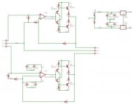
Here is a simplified schematic of a small power amp that could supply 10-15 Watts. The idea would be to use it for tweeters, headphones etc.
The design is certainly not original. I have seen IC buffers that use the same idea. Chances are one of you makes a version of this amp.
R1 & R2 set the bias of the output stage. R3 & R4 are small
Assume a good op amp and appropriate current sources (probably the 2 transistor method).
My question is has anyone built this kind of amp and did it have reasonable performance? Somewhat better than a typical National power amp IC?
Attachments
I thought about a bias variation as well, but not about a solution.
The bias voltage setting is fairly simple with the current circuit but will vary considerably over temperature. This will probably mean more allowable power dissipation than ideal.
I suppose I could add a Vbe multiplier between the Q3 and Q4 bases.
The bias voltage setting is fairly simple with the current circuit but will vary considerably over temperature. This will probably mean more allowable power dissipation than ideal.
I suppose I could add a Vbe multiplier between the Q3 and Q4 bases.
I have build sometime ago as a headphone amp. It can even drive my Tangband well.")
Yours really is the classic op amp buffer version.
Did you like the results? Have you compared it to anything?[
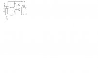
I've built severaal of these simple amps with great success and good sound. I used the lm833n because i had them around. This circuit simmed a nice .00075% thd under multisim 8 pro and the sound reflects the low thd numbers ,although in a built circuit is much higher im sure, 100db sensitve speakers tell all.
sorry for the bad picture but you get the idea.
sorry for the bad picture but you get the idea.
Attachments

I haven't looked at heat dissipation issues yet. I have never been too satisfied with Vbe multipliers that are mounted on the heatsink since there is too much heat lag in a heatsink.
OTOH, if TO-92 transistors were used for the Q1 & Q2, they could be glued to Q3 & Q4 since they have leads. The mounting problem of another Vbe multiplier doesn't go away, so this may be a good solution.
I guess I should build one and see how much the bias varies. I like the simplicity of this amplifier.
I could reduce parts by using constant current diodes instead of the familiar transistor circuits. I'm not sure this is really necessary since the parts count is still quite managable.
Most of my designs tend to have lots of transistors, so this is a bit of a departure.
I've built the circuit from the following web page and I'm very impressed with the results. This is after listening to a SE 2A3 tube amp for a few years and fiddling with LM1875 & LM3875 gainclones for awhile. I changed the Q3 + Q4 to higher fT devices and but had to add a 470 ohm resistor between pin 6 of the op-amp and the base of Q1 to avoid oscillation. Tried a few different op-amps. I also lost the zobel at the output. one of these days I'm going to build a bridged version.
http://redcircuits.com/Page1.htm
http://redcircuits.com/Page1.htm
I used the same topology to build a wideband antenna buffer for a longwave receiver. Works great, and has way more BW than is actually needed. The main difference is that I used +/- 9.0Vdc for the output and +/- 27Vdc for the input to increase the input impedance for use with Hi-Z tuned loops.
danville,
your diamond buffer design is very nice. If you are going o use it for a H/phone amp (so load tytpically 32 Ohms) here are a few suggestions
1. Ditch the current sources and replace them with resistors. Select the resistor value so that the nominal current through the buffer transistors is about 10mA with your cohsen rail voltages
2. Replace R1 and R2 with schottky diodes (Vf is about .2V) like a BAT54
3. Select the value of R3 and R3 for about 30mA (.2V/.03mA), so you will run class A for most of the signal excursion.
4. Use a nice quality op-amp - lots to choose from - LT1028, NE5532/4 etc. You may need a small vallue cap between pin 6 and pin 2 of the op-amp to prevent oscillation due to the pole in the output devices response
5. If you are driving a long headphone cable, I suggest you put a resistor in series with the output (junction of R3 and R4) of 3 to 5 ohms to isolate the cable capacitance. If you don't like the idea of this, a 3-5uH inductor and 10 Ohm parallel damping resistor will do the trick as well.
6. For h/phone use, I would not worry about thermal compensation other than mounting Q1/Q3 and Q2/Q4 and the schottky diodes close to each other. PCB tracks make a wonderful heat conductor chip to chip if you mount them in close proximity.
7. For driving real world speaker loads (3-8 Ohms), you'll need to do a bit more work because of the thermal issues.
Good luck with your project.
Responses to Bonsai:
1. I disagree with this suggestion. For a headphone amplifier where the current is low, the rails will be fairly ideal. If it is a 10-15 watt amplifier, the supply will have ripple on it. This is a source of unintentional feedback to the first follower. If the resistor is replaced with a diode as Bonsai suggests in 2., this effect will be significantly smaller since the voltage will be Vopamp less Vbe & diode drop. A current source loaded follower should be better.
2 & 3. This is an excellent idea. I like the BAT54 idea. I use these parts all the time. An extra diode like a 1N4148 is going to bias the amplifier hot. This is probably doable for headphones but not a speaker amplifier. You would have to make either base Rs or emitter resistors in the output stage large to set the bias current safely. I prefer to keep the output stage Rs low.
4. Assumed, I will probably use a LM4562 (for two channels). I haven't forgotten compensation issues, etc. I drew a simplified schematic.
5. I omitted the load compensation (Zobel, etc) in the simplified schematic. A real amplifier would have one.
6 & 7. My amplifier aimed at driving tweeters and maybe midrange drivers in bi or tri amped systems. I am thinking of using a Amveco toroid (the encapulated PC mount type) on a PC mount with some kind of heatsinking. I haven't got that far. Has anyone looked at the small heatsinks used for PC CPUs (without the fan)? They may be too small. I haven't looked at this yet.
Thanks Bonsai for the ideas. I think I will use your diode suggestion (probably with a current source)
Al Clark
danville, the idea for eliminating the CCS was for purposes of simplification. However, if you run a simulation using resistors as suggested and inject some noise ( I added 1V of 19Khz on + rail and 1V of 15Khz on - rail) the increase in distortion is negligible - probably because the emitters of the followers are 'held' tightly in place by the op-amp on the bases.
This topology (i.e. diamond buffer) is great for driving high load impedances of a few hundred ohms and up. To drive low loads like speakers, you have to keep the output emitter resistors low so the base offset has to also be low and thermally track and this is where the challenge is. This arrangement forms a output stage current limiter by the way.
This topology (i.e. diamond buffer) is great for driving high load impedances of a few hundred ohms and up. To drive low loads like speakers, you have to keep the output emitter resistors low so the base offset has to also be low and thermally track and this is where the challenge is. This arrangement forms a output stage current limiter by the way.
Ipanema said:I have build sometime ago as a headphone amp. It can even drive my Tangband well.
danville said:Yours really is the classic op amp buffer version.
Did you like the results? Have you compared it to anything?
Yeah, danville.
Op-Amp controlled Diamond output stage.
Schematic:
http://www.diyaudio.com/forums/attachment.php?postid=1169803&stamp=1175047572
Super Nice headphone amp idea, Ipanema
It doesn't take more to make Hifi Quality at Highest Possible Level.
.... and go on overdoing and complicate amplifiers is more likely to ruin sound perfomance
as well as often induce new sources/causes of distortions + problems
Good working !
- Status
- This old topic is closed. If you want to reopen this topic, contact a moderator using the "Report Post" button.
- Home
- Amplifiers
- Solid State
- 10 watt Simple Power Amp