I just bought a very nice Sansui TU-9900 at a fair price. It is working perfectly.
The supply in mine was already repaired. TR01 and TR02 were replaced by NT152, see http://www.nteinc.com/
Check also these two sites:
http://www.antennaperformance.com/ mods section TU-9900
and this one in japan, but really good pictures of the restauration process: http://amp8.com/radio/tr-tuner/tu-9900.htm
I was planning the following restaurations, mods:
Replace all supply electrolytic with Panasonic FC,
Replace all Electrolytic in the audio path with BG
Replace 2 TA7136P op amps with OPA2604. I may build a small interface PCB to do so.
Install IEC320 AC connector and shielded AC cable.
Replace the supply rectifier diodes with fast discrete recovery diodes
Replace feet with good EAR one, as use with Bel Canto gears.
I have all the test gears to fully retune it, so I'll do that also.
I will describe the restauration process. It my be of some interest to others.
I've been with this tuner for a few days now, preparing and studying the schematics. First, for the price I paid, 525U$, it is a hell of a tuner. I worked for years in the RF field, and this tuner is a real beauty. It is almost a test equipment receiver. The front end section is a piece of art.
After reading the suggestions for mods on http://www.fmtunerinfo.com/DIY.html, I decided also to install a AC snubber circuit at the AC input ( two 10 ohms/5W resistors and 0.01uf, 400V caps). I will also insulate the power transformer from the case to reduce leakage current as decribded in the article.
Before replacing all the electrolytic caps, I studied the circuits, to determine what to use and where. First, there is more than a few type of caps used throught out all the circuit. I've been working for long enough with this kind of circuits to know that the engineers of these days were using all kind of tricks to improve analogue circuits. Some type of caps are used for a very specific reasons (low leakage, specific temperature drift or compensation, etc). It not always advisable to exchange capacitors type into RF analog circuits. It is even more critical with ceramic caps. Type NP0 or NP7 cannot be exchange for example.
I found that my version of tuner used 4 types of electrolytic and a few tantalum:
Blue Nichicon: Supply filtering
Grey Elna: Supply filtering and circuit used (coupling, osc, etc...)
Grey Elna Non-Polarize (NP): Audio Couplig
Orange Elna: Very specific circuit location (more on that later)
Tantalum: Very specific circuit location.
The Supply decoupling caps are no brainer. I will use Panasonic FC and a few Black-Gates.
The BG will be use at the supply PCB output caps. I will also increase the first filtering caps (C6-C7) and bypass them with WIMA MKS film caps. I won't bypass BG, they usually don't like it. A few of these caps are use in none critical section such as Power-On led supply filtering. I won't change those since they won't add anything to the sound.
For the NP caps I will use Type N, Black Gate, I will also increse their value from 10 to 33uF.
Since I don't know the design criteria for the circuit specific caps or how their value or specs may affect the circuit, I will keep them. It is the same for the tantalum. In one application they are part of a RF circuit. The two other caps are used only for the Low-Pass filter button selection, a rarely used function anyway. Changing them can change the filter parameter. So I keep these 4 tantalum caps as well.
I will post an extensive Excel file that list all my findings, type of caps, value, application and changes suggestions.
I already order the BG caps and the EAR feet. I have all the FC caps in stock.
Before exchanging parts I will test the tuner and measure its specs.

Hi Netlist. I hope it will be interesting. Well, before any measurements, the listening impressions. As noted on some other forums, I have to agree, the sound is great just like it is in many aspect, but some others can be certainly improve.
First the good part:
-Immediate and incredibly living sound. Just listen to people discussion. Voices are natural, fast, crisp. The sound is so there. It is no digital for sure.
-Timing is lightning fast, right on the beat. Music just swing.
-Sound stage is huge.
-Sensitivity: just one word, incredible! Without any antenna conencted, just sitting there in my basement I received plenty of stations. My better than my NAD 4300. With my noce little Dynalb antenna, I will receive the signal strong as a rock.
Things to improve:
-Bass is full but can be better controlled --> Supply improvement?
-Highs sound solid state --> Probably to old opamp and coupling caps.
-Medium also can be more sweet --> op-amp and coupling again.
Problem on my own tuner, Power supply ripple noise. Traced it to the repaired supply. In fact a not so well repaired supply I'm afraid. Noise is coming from the +13V, ripple of 70mV! I replaced this supply with my own bench supply and no more noise. Just silence. Need to work on this one. Since this supply is very basic, I may replace the +13V regulator with a more modern LM317 regulator.
The audio noise dissapear if I supply the +13V with my own supply just the MPX and Low Noise Ampl PCB. The rest of the circuit probably has RC sub filters that remove the ripple.
More on the caps. Reading some more I found into the original parts list that there is 3 types of electolytic caps. The one in Orange are "Low noise" cap. I may keep them. There is just a few.
The two 1.5uF tantalum are not used for the LPF function, as I originally thought, but rather to couple the last RF subcarrier to the MPX decoder output to the LPF module just before getting decoced Stereo FM audio. They probably used tantalum cap to get hi freq response and large capacitance value. So they must have a big impact on te final sound. I really need to replace those.
Just found locally some nice film cap ERO MKT1817, 0.47uF, 63V. They are probably much nicer on the sound. I have also 0.47uF, Wima MKS-3 caps. I will combine three of them in parallel to get 1.5uF, try both and compare the sound. I would expect that they will perform better that these awfull tantalum ones.
Found also the perfect caps for the new snubber I want to install at the AC inlet. They are 0.0047uF, 400V, X1 caps. I'll use two in parallel to get about 0.01uF. The X1 specs is important because they are approved to be used directly on the line voltage. It is a must, see this nice site for details: http://www.justradios.com/safetytips.html
Quote from this site:
"Class X capacitors are used in “across-the-line” applications where their failure would not lead to electric shock. Class X safety caps are used between the “live” wires carrying the incoming AC current. In this position, a capacitor failure should not cause any electrical shock hazards, rather, a capacitor failure “between-the-lines” would usually cause a fuse or circuit breaker to open."
"Class Y capacitors are used in “line-to-ground” (line bypass) applications where their failure could lead to electric shock if a proper ground connection were lost. The failure of a “line-to-ground” capacitor would not open any safety fuse. In other words, the failure of a line bypass capacitor could create a 120 volt “hot” chassis that could give you a potentially fatal shock."
Algar_emi said:The two 1.5uF tantalum are not used for the LPF function but rather to couple the last RF subcarrier to the MPX decoder output to the LPF module just before getting decoced Stereo FM audio. They probably used tantalum cap to get hi freq response and large capacitance value. So they must have a big impact on te final sound. I really need to replace those.
Don't be so eager to replace those "old" parts. Some of them are much better sounding than present day substitutes. When I was modding Accuphase T-101 I put back some of the blue tantalums into signal coupling as they were better than BG N. So always compare the sound of new vs old for best results. I was also very selective about other parts replacement.
I also have TU-9900 and did some mods to it, might post some pics later. Make sure that deemphasis switch is set correctly, it should be 75us for America and it is often set incorrectly (like in my T-101)
After modding, TU-9900 sounds pretty close to TU-X1, but TU-X1 does not not need any mods (except for potentiometer bypassing) to sounds great
")
I measured ripple on the stock supply and its +/-30µV on the +13V side and +/-120µV on the -13V side.
I only changed the caps. Apart from the PSU capacitors, I replace the output opamps with two OPA604's and bypassed the output caps.
I plan to change the dial lamps with LEDs as two are broken and impossible to find.
Nice research you did BTW.
/Hugo
I only changed the caps. Apart from the PSU capacitors, I replace the output opamps with two OPA604's and bypassed the output caps.
I plan to change the dial lamps with LEDs as two are broken and impossible to find.
Nice research you did BTW.
/Hugo
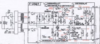
Thanks for ripple measurments NetList. I would like some more voltage readings from the supply circuit if you some time. They are:
Supply Vinput (after D01, before R03):
After R03 (TR01 Collector):
TR03 Base:
TR05 Base:
ZD01 Voltage : (I guest this is a 6.2V)
TR04 Base:
You kept the output caps, just bypass them?
Bye.
Thanks in advance.
Supply Vinput (after D01, before R03):
After R03 (TR01 Collector):
TR03 Base:
TR05 Base:
ZD01 Voltage : (I guest this is a 6.2V)
TR04 Base:
You kept the output caps, just bypass them?
Bye.
Thanks in advance.
Supply Vinput (after D01, before R03):
This is an unregulated voltage and depends from mains voltage: 22.66VDC in case the voltage selector is put on 240V and 25VDC with the selector at 220V
After R03 (TR01 Collector):
Again unregulated:
220V: 23.4VDC
240V: 21VDC
TR03 Base:
15.44VDC
TR05 Base:
6.73VDC
ZD01 Voltage : (I guest this is a 6.2V)
6.17VDC
TR04 Base:
14.03VDC
Outpout caps are still there, but bypassed.
/Hugo
Hi Netlist. Thanks a lot for your fast reply. There was something very wrong with this supply. As I said it was repaired, but not correctly.
Regulation was not working correctly. If I changed the load, the output voltage was changing. TR01 was heating a little too high for its heatsink. R03 value was chnaged from 10R to 40R. Putting 10R back was causing the output voltage the go too high. So I guest, the guy that repaired this tuner replaced the transistors, had some problem to get the output voltage right, then he increased R03 to compensate. Not great. R03 was also very hot.
I looked around and found that TR03 was not conducting. I removed it. It was the right type 2SC1364. I checked it using my trusty DVM with HFE tester. The pins were e b c, but they were connected on the PCB marqued e c b! It was also a brand new transistor and tested Ok! So, this one was replaced too, but the pins assignement was not as the original. By connecting it this way, it was not working right! I put it back to the correct pins location, then Voilà! I replaced R03 to the right value of 10R, 2W.
The supply is now working just fine. TR01 and R03 are no longer hot, just slightly warm. The positive regulator is regulating now, changing the load has no effect on the output voltage. The ripple voltage is now gone too. The noise one the audio output is gone too. Great it is working just fine now.
I measured:
POS: +13.1V, ripple 2mVac
NEG: -13.1V, ripple 2mVac.
I took some measurements using my HP 8640B RF signal generator as FM source.
Left and right channels measured the same. These measurments also assumed that the 8640B is not adding distorsion of its own.
Vout 1V Vout 0.5V
THD 0.12% 0.05% (1Khz)
THD (10Khz, 0.5V): 0.11% (FM deviation was increase to compensate for the deemphasis) response curve. It was set correctly to 75uS.
Deemphasis Curve (20dB per decade, 2-20Khz) = 19.8dB, not bad
1Khz, 0dBV (Reference)
2Khz = -1.9dB
4Khz = -6 dB
8Khz = -12dB
16Khz = -18.1dB
20Khz = -21.7dB
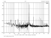
I used my Clio system to do a FFT analysis at 1Khz, 0.5V.
Noise floor is as low as the CLIO system, at -120dBV, not bad
The 60Hz ripple from the supply is at -84dBV. I'll see if by replacing the supply rectifier diodes with soft recovery diodes and upgrading the supply caps, the noise floor and 60 hz peak came be lower. They may come from my signal generator also.
But it seems pretty hard to improve already.
I listen to a strong carrier without modulation and the noise floor is soo low, as the measurement are showing, that is perfect silence.
Attachments
- Status
- This old topic is closed. If you want to reopen this topic, contact a moderator using the "Report Post" button.
- Home
- Amplifiers
- Solid State
- Sansui TU-9900 Restoration and Mods