and hopefully that doubled barrel shotgun might be put aside for this one.I really encourage the inquisitive builder out there to try this circuit. Its essentially a blameless with some changes in error correction and current sourcing. If you have access to the same parts as listed all the merrier as the vas transistor is somewhat critical..You will be rewarded with effortless and music tones, with images that can often jump out at you with startling realism. The best part is that they comewith no ear fatigue at all over long listening.
Attachments
Hi vynuhl.addict,
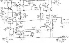
That is a similar topolgy to Douglas Self's 'Blameless', but it does not follow Self's closed NFB loop stabilisation strategy.
Your circuit does not have the single 100pF Miller connected C.dom which so slows VAS control of the output devices when driving real world loudspeakers.
Good to hear that you have this genuinely useful topology sorted, as indeed Carlos has in his own Dx thread with a more simple design. Your 2SA1360 needs overcurrent protection though, because with an inadvertent fault condition it could conduct itself and the top half of the ouput stage into instantaneous self destruction with that Darlington drive.
Cheers ......... Graham.
Oh!...a new blamefest!....were is my gun?
Mine was not good...maybe other one constructing....maybe i have made some mistakes...sounded without salt...i turn very nervous..really i am still nervous with that design.
I was expecting beautifull sonic results...i felt myself stupid as a mule constructing that one and trying to make it sound fine.
Grrrrrrr!....i cannot see that...i turn nervous once again!
Kidding...Doctor Self is a nice guy with good designs...maybe i am deaf!
C'a marche soldat...defense l'arrière!
regards,
Carlos
Attachments

vynuhl.addict,
As pointed out correctly by Graham, the Vas transistor needs protection - you could take the cue from D.Self's many circuits.
Taking the cue from Self a little further, why not use bootstrapping for the input like he did with his Load Invariant Amplifier?
Your schematic does not show the transistor types for the Current Source and Vbe positions. The input stage decoupling resistor value is also not shown. (Can the same resistor not be replicated in the negative rail as well?)
The 20K resistors to ground from the current sources on the negative rail can be split into 10K+10K and the junction can be decoupled with caps.
Tell us more about the sound and to which amps did you compare.
I remember that one i have made...not this one that seems to be good
But that one was terrible
I leave in front of the beach ...and i have recorded that sound...the sound of waves when they are intense... a digital high quality recording was made.
And i remember that i have reproduced that noise...and others too..but this one....result terrible!....the wave sound seemed to me to be air leakage from an automobile Gaz Station tire inflation machine.
This is the reasons of my scandalous reaction to "that" amplifier.
Observe my place....for sure i know the wave sounds quality... it is constantly playing inside my ears...and recording played with other amplifiers, as Symassym...GEM....mine and others sounded nice.
regards,
Carlos
Attachments

Graham, overcurrent potection such as a 10ohm resistor between emitter of vas and rail?. I took a hint in one of Hugh Deans posts to try out bare minimal lag, and secure with lead comp, needless to say this made a difference that was no less than stunning in sound quality differences, gone was that well documented solid state hardness. Even when I built the oiriginal blameless i used a 47pf cap instead of 100.
Carlos, you points on the original blameless are very valid, It is clean, very clean but unable to allow long listening without breaks.
The input stage decoupling resistor is 10ohms 1/4 watt. The VBE bjt in 2sd600k Sanyo, current source bjt are 2n5551 nos motorola. my goal was still aimed at simplicity while constructing, and in dougs designs he only decoupled one half with a resistor also but i am not sure of his reasoning. The original reason i did this was because i saw it done in the trimodal .. I suppose it could be replicated in the other rail but as far as tweaks go with this amp it sounds very finished. It is currently being run from a dual mono supply but using one 300va transformer and 24000uf per amplifier. The Rails sag very little at high levels(not ear bleeding), less than a volt +/- 500mv or less variation.
Hi vynuhl.addict,
I would suggest half the value used in the opposite sink, which comes out closest to 33R, and use the voltage dropped across this to drive a current limit with emitter to rail and collector to the base of the 2SA1145. Use a very low capacitance PNP small signal transistor for this.
Enjoy your listening.
Cheers ........ Graham.


No differences Johan...we have only the Atlantic Ocean between us.... the same
result is possible...difference may be the constructions we have around...brazilian style...but the beach beauty, by itself is not a Brazilian Monopoly.
Hawaii....Honolulu...Kaneohe....Waikiki is much better!
regards,
Carlos
result is possible...difference may be the constructions we have around...brazilian style...but the beach beauty, by itself is not a Brazilian Monopoly.
Hawaii....Honolulu...Kaneohe....Waikiki is much better!
regards,
Carlos
Attachments

It is an amplifier, with a gain of 23 or 27db.
Another question for Graham, for the the overcurrent bjt the smallest capacitance bjt i have on hand is 2sa1145 with a 50ma rating, would this suffice??. I want to use something that will have no detrimental effects on sonics at this point ..I originally blew a a1360 when first built after accidently shorting the vbe multiplier to the heatsink and subsequently ground (due to a very small shard of aluminum after drilling the heatsink), you are right in the respect of it will take it out instantly, but the output stage is very robust with mje15032/33 and mjl3281/1302..
Thanks
Colin
The answer to your question is too big to be done Aguantesoda
reason why people do not came to answer you.
To answer you, the whole circuit philosophy will need explanation..this is long and hard.
Mateus is a nice guy...his answer could be just kidding...as the logical sequence, or the most possible answer... respecting the rithm of language.... could be this one.
Say..some obvious answer that people use to give..depending of the culture, of course...for instance..the question...What to do with my finger?...well, the consequence is obvious..if i do not know what to do with it..people will say.. at least in my place:
- Why don't you trow it.............inside you ears for instance (hehe)
Tweaking something that may be problematic, circuit that is known by Mateus (deeply experience guy) as a problematic one...may still result a little problematic....so...result nothing related advantage, profit or happyness resulted of this work...this can be one of the possible meanings.
He is nice..for sure he is..do not bother because, for sure, his aparently acid answer is result of our misunderstanding of his word's meaning.
They are fine...good guys...circunstances were not so good...remember that ...even if they would not be so nice..they are few persons..our forum has more than 70 thousand folks...feel good with the others 69998 folks.
But they are nice.... guaranteed they are nice.
regards,
Carlos
J mateus is right, this circuit does nothing, that is nothing that it shouldnt do. It provides an avenue to amplify music in a very convincing and meaningful way, to cut through the BS and ley you sit back, relax and understand what is put forth both tonally, texturally and rythmically.. Those you frown upon and point fingers should first build it(with the same parts) then cast judegment beyond the obvious being a semi standard 3 stage design..
Colin
Colin
Yes Vinyl...no one can judge an amplifier without listen to it, comparing with a good
reference unit, in a fair A to B blind testings.
The amplifier must be constructed following the designer instructions, the board have to be the one supplied by the designer, the parts have to be the ones suggested and the speakers used for testing need to be very good ones...and also, replaced by other good ones during A to B listening and comparing testings.
I also think....alike you think...that, without those testings, people have not the rigth to say nothing about evaluation...or...at least... i will be entirelly sure that the one do not know what he is talking about.
Without those kind of testings....in my personal judgement, words about every amplifier are "empty"...having no value to me.
Also, it is not a responsable behavior.
Unfortunattelly, for evaluation purposes, there are people that visit friends in House A....and next day visit another friend in House B....having space of time to fool himself...having listening environment different...having different social moments, different mood...well....a very bad conditions to compare something....and some guys deer to express evaluations having those kind of experiences.... non sense and not responsable way to judge things.
Well...John Mateus told nothing....and this is all he said...we cannot know his meaning...but for sure was not a critic about....he was kiding for sure...the guy is nice.
I am just supporting your idea and posting mine too.
Thanks to let us know your ideas and your schematic.
regards,
Carlos
Thanks Carlos,
I wanted to be sure I could live harmoniously with this amplifier before I posted the schematics, a month has told me that it is possible. Secondly I became determined to do what I could to make the blameless topology a musical topology rather than an as you say"gas station air pump leak" when playing back the sounds of the ocean \), thanks for the inspiration Carlos..I believe this amplifier speaks very strongly against high value miller compensation and very strongly for phase lead and miller. What has really gotten me on this project is how some simple changes in the second stage makes the biggest differences, for a mere 20 cents more one SM cap and an extra transistor. Since I painstakingly drew out the original boards by hand and etched them I will have to make two new boards with some new ideas from Graham, I have 20 mje15032/33 on the way and a couple rails of mjl3281/1302 left over fortunately so i wont have to pilfer from my present boards.
Thanks
Colin
I wanted to be sure I could live harmoniously with this amplifier before I posted the schematics, a month has told me that it is possible. Secondly I became determined to do what I could to make the blameless topology a musical topology rather than an as you say"gas station air pump leak" when playing back the sounds of the ocean
\), thanks for the inspiration Carlos..I believe this amplifier speaks very strongly against high value miller compensation and very strongly for phase lead and miller. What has really gotten me on this project is how some simple changes in the second stage makes the biggest differences, for a mere 20 cents more one SM cap and an extra transistor. Since I painstakingly drew out the original boards by hand and etched them I will have to make two new boards with some new ideas from Graham, I have 20 mje15032/33 on the way and a couple rails of mjl3281/1302 left over fortunately so i wont have to pilfer from my present boards.Thanks
Colin
Hi vynuhl.addict
I agree with your objectives but wonder whether the circuit you posted really works as it says.
First point I'd make is that the 10 pF is a lot smaller than Self's 100pF -as Graham already said. This puts the "Miller" effect ten times higher in frequency (i.e. less effect on audio) than in the blameless.
Second point does it oscillate? Simulations using BD139/140 VAS, drivers says it does. Not badly (just a little, so maybe not noticed) Perhaps your 33pF can be made smaller....maybe only needs to be 15 pF with MJL3281 etc.
Maybe the circuit is OK with the transistors you specify. I have not got models for those, but BD139/140 seem representative of many HF transistor types (ft ~100 MHz). If the VAS is slower, maybe already slows down the VAS without Miller capacitor ?
cheers
John
- Status
- This old topic is closed. If you want to reopen this topic, contact a moderator using the "Report Post" button.
- Home
- Amplifiers
- Solid State
- A cirucit to put Carlos anti-blameless stance to permanent rest.