Hi there,
Recently I bought NAD 2200 for fairly price less than 100 Eur.
The first step was to replace caps In power stage and first surprise there is two 10 000 uF/120 V caps and its almost impossible now days to get this kind of capacitors, so I decided to replace them for 10 000 uF/ 100 V (very risky I know that..;-))but suddenly speakers relays has gone, at this moment I am considering to perform general mod of power stage and speakers circuit.
I would like to replace original transformer for two separated toroidal transformers (audio version, one for each channel) and replace original speaker relays for some kind of circuit to secure speakers from DC voltage.
I am looking for ideas how to perform this operation schematics, etc.., may be someone have done similar mods for similar NAD power amplifiers ??
I will really appreciate any ideas ..
Best Regards,
Art
Hi,
what voltage is coming out of the transformer?
I would be surprised if you can get over 100Vdc even when all the amps are disconnected and mains is running at maximum tolerance.
Two smaller toroids will not perform a s well as one bigger toroid.
and they will take up more space and cost more. Keep the existing toroid or replace it with a bigger ONE for more performance.
Does the 2200 have a mix of various secondary windings/tappings?
Hi,
Tank you for replay,
NAD 2200 does not have a toroid but “standard” transformer which for some rison make quiet “brummmm” sound (I have checked very cheerfully chassis and screws around the transformer if something is loos. I suppose this is a “age” effect and lofts of hours playing).
Because this sound is very annoying I want to get rid off all power stage including transformer and create new one.
The transformer has two 3 primary windings for different voltage 110/230/250 V and two secondary for 62/95 V.
The idea of using two toroids transformers was to separate power supply for each channel to get better results in overall sound, and I can order custom transformers and specify voltage so technically is not a problem. Off course the question is if this idea is ok I am not going to spend more money for nothing. So if you suggest to leave one big enough transformer to power up two channels it is ok for me .;-).
I am looking for contact with persons who perform similar changes and get some ideas/advices because I would prefer to do not fry my power amp during the experiments ..
Regards,
Artur
Yep,
I know that I am balancing over the edge and I am very close to blow up caps ;-)
That's why I created this topic ..
General idea is.
1) New toroid transformer
2) drop voltage about 5 V on the 95V circuit
3) change relays in loudspeakers circuit for more common
But I have no idea how those steps will impact sound quality
May there is no sense to do all listed mods, may be the better idea is to take chassis and some part and make GainClon Apleph or something similar ??
Regards,
Artur
I know that I am balancing over the edge
and I am very close to blow up caps ;-)That's why I created this topic ..
General idea is.
1) New toroid transformer
2) drop voltage about 5 V on the 95V circuit
3) change relays in loudspeakers circuit for more common
But I have no idea how those steps will impact sound quality
May there is no sense to do all listed mods, may be the better idea is to take chassis and some part and make GainClon Apleph or something similar ??
Regards,
Artur
Hi,
I now understand why 2200 had 120V caps.
+-95V rails can produce unusable power output.
I suspect this amplifier has an enormous dynamic power overhead.
In my opinion high dynamic overhead is a direct measure of the badness of the PSU and ampilfier.
Much better sounding results will come from a stiff PSU that hardly drops under load and a power amplifier that can deliver the peak current that your worst load requires.
Since you want to make gross changes, can I suggest an alternative?
Buy a new toroid of about double the VA rating of the existing (at least 1kVA).
Specify four tapped secondary windings 0-46-65Vac.
Each pair of windings will give the same power as the total coming from your existing transformer.
However, the 65Vac will just allow you to use 100Vdc capacitors (assuming regulation=3.5% and overvoltage=6%, if that is too close specify 64Vac).
Since the capacity of the transformer is doubled the PSU voltage will hold up better under load and although the amplifier appears to run with a lower supply voltage it will produce higher power on longer term transients and much more power on continuous loads.
The multi winding secondary will give some improved isolation between channels, slightly better than using a dual PSU off a single centre tapped winding and very much better than a single PSU off a single transformer.
Even the 46Vac tapping will give supply rails of about +-65Vdc and a good amplifier will produce about 200W + 200W into 8ohms (+-20mF/ch). If both the amp and PSU are designed appropriately about 350W +350W into 4 ohms (+-40mF/ch).
If you agree that high dynamic overhead is an advertiser's con trick, then do you need the higher voltage rails and the complication that switching them on entails?
The better PSU will allow you to put more stress on the amplifier and a very good PSU may allow the amplifier to blow itself up if not protected for the new duty.
Think it through and either do the numbers yourself or find someone who has done the numbers before you.
Hi,
Take an example.
Let's assume the output stage can supply 200W into 8ohms continuously. that is 56Vpk and 7Apk into 8r0.
Two channels off the power supply require peak currents of 14Apk from each rail, alternately.
The PSU smoothing caps need to supply this peak current and the transformer tops them up using very short high current pulses.
The transfomer can be rated to meet this requirement by choosing the VA rating~= 1times to 2times the total output power. For the 200W case this is 400times 1.5=600VA.
To produce that level of power one needs 45Vac to 50Vac depending on how well the amplifier sends current to the load. Assuming 45Vac and 600VA, the Iac=6.67Aac. The maximum continuous DC current from the PSU is approximately half this at about 3.3Adc.
If the output stage could survive 350W into 4ohm continuously then the numbers come out rather differently.
VA=1.5*(350+350)=1kVA (the figure I gave you earlier).
Iac=11.1Aac, but what use is knowing the AC current from this transformer?
Note all this is based on using the lower voltage tappings on the transformer.
If you intend using the higher voltage tappings then the output stage could produce somewhere in the kWs of output. If you were to design the PSU to meet XkWs then I suggest that the 2200 will blow up long before you get anywhere near maximum output.
Forget about high dynamic power. It's a cheap way to give out impressive figures that mean almost nothing for sound quality.
depends on the SOAR of the output stage that NAD put into the amplifier.amperages of secondary windings
Take an example.
Let's assume the output stage can supply 200W into 8ohms continuously. that is 56Vpk and 7Apk into 8r0.
Two channels off the power supply require peak currents of 14Apk from each rail, alternately.
The PSU smoothing caps need to supply this peak current and the transformer tops them up using very short high current pulses.
The transfomer can be rated to meet this requirement by choosing the VA rating~= 1times to 2times the total output power. For the 200W case this is 400times 1.5=600VA.
To produce that level of power one needs 45Vac to 50Vac depending on how well the amplifier sends current to the load. Assuming 45Vac and 600VA, the Iac=6.67Aac. The maximum continuous DC current from the PSU is approximately half this at about 3.3Adc.
If the output stage could survive 350W into 4ohm continuously then the numbers come out rather differently.
VA=1.5*(350+350)=1kVA (the figure I gave you earlier).
Iac=11.1Aac, but what use is knowing the AC current from this transformer?
Note all this is based on using the lower voltage tappings on the transformer.
If you intend using the higher voltage tappings then the output stage could produce somewhere in the kWs of output. If you were to design the PSU to meet XkWs then I suggest that the 2200 will blow up long before you get anywhere near maximum output.
Forget about high dynamic power. It's a cheap way to give out impressive figures that mean almost nothing for sound quality.
Hi,
just did some manual calcs on a real device the MJ15003.
I figure the changeover from power de-rating factor to second breakdown de-rating factor moves from the 25degC knee @ 50Vce to about 66 to 67Vce, when Tc is set to 87.5degC (chosen to make for an easy to apply power de-rating factor=0.5).
The result of this is that below 66Vce or 67Vce the power (250W) is derated by a constant 0.5.
Above 66Vce or 67Vce the second breakdown line is de-rated by 0.8.
The new knee (for Tc=87.5degC) occurs at ~156W*0.8 ~= 125W @ 66Vce giving a peak current of about 1.8Apk (125W also =250*0.5).
This is considerably higher than the power de-rating factor times Ic ~=1.18Apk. An increase of 52% at this particular Vce and well into the region of second breakdown.
This is equivalent to saying that second breakdown does not apply below 66Vce when the device Tc is at an elevated 87.5degC. Surprising conclusion!!!!
Do any other manufacturers advise a similar or different assessment of SOA in the second breakdown region when Tc de-rating needs to be applied?
Hi Cypher,
since you are replacing both transformer and smoothing caps.
Consider the cost of 63V vs 80V vs 100V capacitors.
Your new transformer could be specified to just allow maximum voltage into one of these limits.
40Vac for 63V caps
51Vac for 80V caps
64Vac for 100V caps.
As the voltage is lowered so the low impedance drive ability of the amplifier improves. The down side is reduced power into high impedance loads set against extra power into low loads that otherwise may overstress the output stage.
Hi
Endrew, thanks a lot for feedback .;-))
Things are becoming more and more complicated. At glance I thought that dis mod will be easy ..
So I have to ask someone more experienced for help to solve this issue..
I have found several topics on different forums regarding relays and power supply in old NAD products, my be this topic will help solve common problems vantage NAD power amplifiers..
Any ideas are welcome..
Back to my ideas:
I would like to drop voltage from 95V to 80-85V, designed new toroidal transformer and find solution for relays (new circuit with new relays ??)
Max power is no issue because I am listening music with max power 8-11 (knob setup..-))
If idea with lower voltage is ok, is any one is able to help me and calculate parameters for new transformer ???
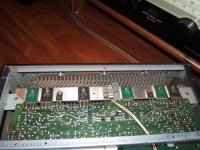
Andrew you have asked question in email there is 9 transistors (have a look at attachment..)
Regards,
Artur
Endrew, thanks a lot for feedback .;-))
Things are becoming more and more complicated. At glance I thought that dis mod will be easy ..
So I have to ask someone more experienced for help to solve this issue..
I have found several topics on different forums regarding relays and power supply in old NAD products, my be this topic will help solve common problems vantage NAD power amplifiers..
Any ideas are welcome..
Back to my ideas:
I would like to drop voltage from 95V to 80-85V, designed new toroidal transformer and find solution for relays (new circuit with new relays ??)
Max power is no issue because I am listening music with max power 8-11 (knob setup..-))
If idea with lower voltage is ok, is any one is able to help me and calculate parameters for new transformer ???
Andrew you have asked question in email there is 9 transistors (have a look at attachment..)
Regards,
Artur
Attachments
If you want my opinion, don't alter anything.
The main purpose of the 2200 was to be able to deliver huge amount af power in a limited time window. It was called "the powertracker". I have used them for PA (20 years ago) and we newer ran out of power.
It's rated 100W, 8ohms continously but will do 400W 8 ohms in up to 1000ms (1 sec.) and 800W (1 sec.) into 2 ohms. It will do 400W cont. into 8 ohms in bridge mode and 1600W (1 sec.) in bridge into 4 ohms.
To be able to do this it's powersupply and output stage is carefully connected.
PM me, I'll send you the schematics.
on +-62Vdc supply rails and yet only 100W into 8ohms continuously.avr300 said:It's rated 100W, 8ohms continously but will do 400W 8 ohms in up to 1000ms (1 sec.) and 800W (1 sec.) into 2 ohms. It will do 400W cont. into 8 ohms in bridge mode and 1600W (1 sec.) in bridge into 4 ohms.
It seems the output stage is seriously compromised for any decent power even without the high voltage rails.
I see from the schematic/parts listing that 2200 uses 2sa1381/0302
Is it just 2pair in each output stage? or are there more hiding in there?
Hi,
avr300 thanks for schematics your version is more clear then my version..-))
Andrew there is no 2sa1381/0302 transistors, but 2SA3281 and 2SA1302 if so, on schematic and on board is 16 of them, four 2SA3281 and four 2SA1302 on each channel..
avr300 – you mentioned to do not alter anything, do you have any idea how to work around problem
Regards,
Artur
avr300 thanks for schematics your version is more clear then my version..-))
Andrew there is no 2sa1381/0302 transistors,
but 2SA3281 and 2SA1302 if so, on schematic and on board is 16 of them, four 2SA3281 and four 2SA1302 on each channel..avr300 – you mentioned to do not alter anything, do you have any idea how to work around problem
Regards,
Artur
- Status
- This old topic is closed. If you want to reopen this topic, contact a moderator using the "Report Post" button.
- Home
- Amplifiers
- Solid State
- NAD 2200 power supplay help needed