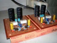
Leolabs said:The schematic in PDF.
Looks very elegant.
Do you have measured results, or listening tests ?
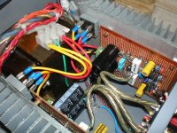
Thank you guys for interested.Even though it just stay at my place for not more than 2 weeks(as a my friend of mine ask me to help him build this amp),still quite impressive with it's performance.
First time set-up at my place:
-Source:a CDROM,a Zoran chipset based DVD player.That's all I have at this moment,planning to buy a H/K HD970 later.
-Speakers:KEF iQ1.
First impression was very powerful bass yet not overpowered,but lack of clarity/details,and not so good at voices(with CDROM direct in).Then swithed to the DVD player which output level is higher,it was a whole different story then.Clarity/details improved significantly and voices(tested with Norah Jones and Frank Miller).Listen to Aaron Copland's Fanfare for the Common Man was fun,wide soundstage,solid
bass.Guess that have to partner it with high output sources/preamps.
Later,my friend brought it to the local hi fi shop(and the people there was quite impressive with this DIY amp) to choose his speakers and finally got himself a pair of Yamaha NS525F instead a pair of Mission due to the $$$ problem,LOL!

Hi Leo,
10A fuses in the supply rails. Try F2A to F3.1A. I think you will find they work into all sensible loads from 6ohms upwards and maybe 4ohms loading as well, without any deterioration in sound quality.
What loading are you expecting the single pair to cope with on these +-50Vdc supplies?
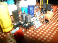
Just +-4.7mF/channel of smoothing!
Try pushing this up to +-10mF/ch minimum and maybe as high as +-25mF/ch for 6ohms and upwards.
Is that 10uF in the NFB lower leg a plastic film cap?
6 diodes (+R) in the bias voltage string.
Are any on the output heatsink?
How does the bias vary with temperature?
No DC block on the input!
No filtering at all on the input!!!
10A fuses in the supply rails. Try F2A to F3.1A. I think you will find they work into all sensible loads from 6ohms upwards and maybe 4ohms loading as well, without any deterioration in sound quality.
What loading are you expecting the single pair to cope with on these +-50Vdc supplies?
Just +-4.7mF/channel of smoothing!
Try pushing this up to +-10mF/ch minimum and maybe as high as +-25mF/ch for 6ohms and upwards.
Is that 10uF in the NFB lower leg a plastic film cap?
6 diodes (+R) in the bias voltage string.
Are any on the output heatsink?
How does the bias vary with temperature?
No DC block on the input!
No filtering at all on the input!!!
6 diodes (+R) in the bias voltage string.
Those are already inside the SAPs.
10A fuses in the supply rails. Try F2A to F3.1A
How about 5A???
What loading are you expecting the single pair to cope with on these +-50Vdc supplies?
Work fine with 'normal' speakers.Still looking for something hard to drive.
Just +-4.7mF/channel of smoothing!Try pushing this up to +-10mF/ch minimum and maybe as high as +-25mF/ch for 6ohms and upwards.
Alright.
Is that 10uF in the NFB lower leg a plastic film cap?
Nope.Just a bipolar aluminium cap.
No DC block on the input!
No filtering at all on the input!!!
Time will tell whether they are needed or not.But points taken.
Thank you guys for response to this thread.Many many thanks!
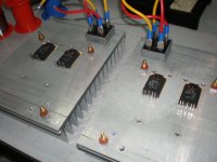
I need some information about the SAP15 N/P. Could you please tell me where you have ordered them? Have you bought them as a private or from a society? Finally, a curiosity, why have you used a such large heatsink for a couple of transistors with integrated temperature compensation network !!!
Have you adjusted the diode forword current at 2.5 mA and the idling currenteat 40 mA with the exernal variable transistor as you can see in the Sanken datasheet?
I hope you'll give me soon an answer. Thank you very much in advance for your kindness.

Have you adjusted the diode forword current at 2.5 mA and the idling currenteat 40 mA with the exernal variable transistor as you can see in the Sanken datasheet?
I hope you'll give me soon an answer. Thank you very much in advance for your kindness.
Hi!
I bought them from Farnell.
Because my friend got them free from a broken Peavey 300SC.
I adjusted them around 100mA.Make sure the current of the VAS stage is more than 2.5mA.
Could you please tell me where you have ordered them?
I bought them from Farnell.
why have you used a such large heatsink for a couple of transistors with integrated temperature compensation network !!!
Because my friend got them free from a broken Peavey 300SC.
Have you adjusted the diode forword current at 2.5 mA and the idling currenteat 40 mA with the exernal variable transistor as you can see in the Sanken datasheet?
I adjusted them around 100mA.Make sure the current of the VAS stage is more than 2.5mA.
I know this thread is ancient.. but does anybody know current requirements for these transistors?
I've got a guitar amp with a complementary pair sap15n/sap15p and the powert transformer is dead, so i'm haveing one custom built.
Any kind of information would be appreciated.
Thanks a lot!
I've got a guitar amp with a complementary pair sap15n/sap15p and the powert transformer is dead, so i'm haveing one custom built.
Any kind of information would be appreciated.
Thanks a lot!
SAP15 and SAP16 pairs are now obsolete. They are now replaced by STD01, 03 pairs.
See Sanken website Any new design should be planned around these, which don't include the emitter resistor as did previous Sanken darlingtons.
I guess you are asking for the maximum current rating rather than current requirements. You will find the relevant specifications in Datasheets like this one: Sanken - datasheet pdf
The amplifier design determines what the requirements are and you should be working from a schematic to determine current requirements for a transformer or any any other part of the power amplifier design.
Thanks for the reply!
I've been reapiring and building tube amps for quite a while but i've never really gotten into solid state designs.
This amp used to run on +/-45V on the transistor collectors before it died. But i have no clue how to determine appropiate current requirements for the transformer.
Will i be ok if I just add the max current from two SAP15 transistors?
Here's a link to the schematic in case you can point something out for me
LANEY LV300-H-TWIN SCH Service Manual free download, schematics, eeprom, repair info for electronics
Thanks again, and sorry for my english.
Martín.
- Status
- This old topic is closed. If you want to reopen this topic, contact a moderator using the "Report Post" button.
- Home
- Amplifiers
- Solid State
- A SAP15 based power amp