" Take out the R and insert L? ..."
Yes. Why not, this is after all a power supply and you are trying to cut down on cross talk as well as noise in the rails. " ... you might wind your own resistor / inductor and put 'er there."
Figure out what the current you want flowing through that "Low R" resistor ... cut off a bunch of resistance wire ~= to that value of R and wind it around a wooden dowel, as many turns as are practical / possible = a nice inductor. ... the exact inductance value is not the issue, but the fact of an inductor's existance is = smack between two fat caps = lots of effect, just like you might find an those commercial power line filters that knock EMF off the power lines = squishes that ol' ripple down to a managabubble level = down a few db
Why buy resistance wire?
just buy a 500gram reel of 1mm enamelled copper wire.
Leave it on it's plastic bobbin and solder the ends between the two caps. Job done.
Aircored inductor for about $10.
If you want to adjust resistance buy 0.9mm or 1.2mm wire. Or for super duty 1kg of 1.6mm wire.
just buy a 500gram reel of 1mm enamelled copper wire.
Leave it on it's plastic bobbin and solder the ends between the two caps. Job done.
Aircored inductor for about $10.
If you want to adjust resistance buy 0.9mm or 1.2mm wire. Or for super duty 1kg of 1.6mm wire.
" ... just buy a 500gram reel of 1mm enamelled copper wire. Leave it on it's plastic bobbin and solder the ends between the two caps. Job done. ..." " ... tick a piece of ferrite rod down the reel centre for up to 40dB of 100Hz reduction ..."
Now that's DIY ...
(Wow !! 40 db !! ... down from the previous noise floor, right ... he, he, he)
Now that's DIY ...
(Wow !! 40 db !! ... down from the previous noise floor, right
... he, he, he)This is why I love this place. I just ordered a bunch of BIG power resistors (10ohm 95W) from the bay, and am going to parallel 4 per rail on my UCD amps (one built, one pending). I was worried about the increasing voltage drop under load, but the diode trick oughta work real trick. I'll bypass them with a small cap to kill the HF noise and use quiet diodes (HexFreds).
Wow this is such an old posting. I ended up buying a bunch of Surplus inductors, and have been using them in various amp builds. To this day, regardless of the amplifier design afterwards, the CLC power supplies have made the best sounding amps with the lowest noise floor I've ever heard or owned. The inductors are potted in shielding cans which helps as well.
I recently finished an amp that used a switching supply. The ripple and regulation is about as low as it gets with these regulated supplies, so I thought I would give it a shot. Kept the supply well isolated, shielded, etc, but it just doesn't compare with the CLC supply. I finally after over a year of futzing got it so that its as quiet as my other amplifier. The amplifier modules themselves are of a better design, so its an overall better amp, but I still feel like I like the old amp better. I'm tempted to try making a CLC supply.
Another option I've toyed with would be to remove the filter inductor's at the output stage of the switching supply, then insert an inductor and capacitor set of much higher inductance and lower ESR at the caps. My understanding is it would likely kill the regulation, but would probably further improve the noise floor, and improve the power supplies ability to react to quick dynamic swings. As is there is already 18700uf's of capacitance. The designer of the supply is telling me I need to add more capacitance to the front end, not the back end, but I think they are more focused on the regulation. I'm not sure the regulation is that important here. Its probably more beneficial for the front end stages of the amplifier, but the amplifier has regulation onboard for that, so I'm not sure its buying much (its good regulation too). The problem you have is building a power supply for rail voltages in excess of 70 volts gets tricky. Parts are readily available for less than that, but I have rail voltages on one amp at 75 volts, and this amp is 106 volts. Findings caps with enough headroom to handle either is tricky. Transformers get huge, expensive, and heavy. On paper these switching supplies look like a god send, but I'm still up in the air. I do think its working quite well right now, and things sound great, but I literally just fixed the last problem this past weekend.
Wow this is such an old posting. I ended up buying a bunch of Surplus inductors, and have been using them in various amp builds. To this day, regardless of the amplifier design afterwards, the CLC power supplies have made the best sounding amps with the lowest noise floor I've ever heard or owned. The inductors are potted in shielding cans which helps as well.
I recently finished an amp that used a switching supply. The ripple and regulation is about as low as it gets with these regulated supplies, so I thought I would give it a shot. Kept the supply well isolated, shielded, etc, but it just doesn't compare with the CLC supply. I finally after over a year of futzing got it so that its as quiet as my other amplifier. The amplifier modules themselves are of a better design, so its an overall better amp, but I still feel like I like the old amp better. I'm tempted to try making a CLC supply.
Another option I've toyed with would be to remove the filter inductor's at the output stage of the switching supply, then insert an inductor and capacitor set of much higher inductance and lower ESR at the caps. My understanding is it would likely kill the regulation, but would probably further improve the noise floor, and improve the power supplies ability to react to quick dynamic swings. As is there is already 18700uf's of capacitance. The designer of the supply is telling me I need to add more capacitance to the front end, not the back end, but I think they are more focused on the regulation. I'm not sure the regulation is that important here. Its probably more beneficial for the front end stages of the amplifier, but the amplifier has regulation onboard for that, so I'm not sure its buying much (its good regulation too). The problem you have is building a power supply for rail voltages in excess of 70 volts gets tricky. Parts are readily available for less than that, but I have rail voltages on one amp at 75 volts, and this amp is 106 volts. Findings caps with enough headroom to handle either is tricky. Transformers get huge, expensive, and heavy. On paper these switching supplies look like a god send, but I'm still up in the air. I do think its working quite well right now, and things sound great, but I literally just fixed the last problem this past weekend.
Inductors for the power level I have are very large and pricey, so I found the cheapest huge power resistors I could and Whoo-bam, done. I agree with you on SMPS, I think regulation for home power amps is not so much of an issue so long as there's plenty of cap in the supply. Proamps would naturally be a different story.
I'll include a diode string with some low-noise Hexfreds or the like and bypass each of them with a small cap.
They would have been for me too. My amps are 200 watts per channel. The inductors I have are capable of passing 8 amps rms each and are good for 120 mh. These were more than enough for my amps. I have enough of them I could do mono power supplies, but for these amps, it was more than enough to have one. I know I know, reduced cross talk, but it was a lot of work to build two.
The reason I didn't do it for the better amp was that they were 300 watts per channel at 8 ohms, 600 at 4 ohms given a sufficient power supply, and I couldn't create a big enough supply with those inductors, even in mono operation. It was just easier to use a 1200 watt SMPS.
The reason I didn't do it for the better amp was that they were 300 watts per channel at 8 ohms, 600 at 4 ohms given a sufficient power supply, and I couldn't create a big enough supply with those inductors, even in mono operation. It was just easier to use a 1200 watt SMPS.
Wow this is such an old posting. I ended up buying a bunch of Surplus inductors, and have been using them in various amp builds. To this day, regardless of the amplifier design afterwards, the CLC power supplies have made the best sounding amps with the lowest noise floor I've ever heard or owned. The inductors are potted in shielding cans which helps as well.
I recently finished an amp that used a switching supply. The ripple and regulation is about as low as it gets with these regulated supplies, so I thought I would give it a shot. Kept the supply well isolated, shielded, etc, but it just doesn't compare with the CLC supply. I finally after over a year of futzing got it so that its as quiet as my other amplifier. The amplifier modules themselves are of a better design, so its an overall better amp, but I still feel like I like the old amp better. I'm tempted to try making a CLC supply.
Another option I've toyed with would be to remove the filter inductor's at the output stage of the switching supply, then insert an inductor and capacitor set of much higher inductance and lower ESR at the caps. My understanding is it would likely kill the regulation, but would probably further improve the noise floor, and improve the power supplies ability to react to quick dynamic swings. As is there is already 18700uf's of capacitance. The designer of the supply is telling me I need to add more capacitance to the front end, not the back end, but I think they are more focused on the regulation. I'm not sure the regulation is that important here. Its probably more beneficial for the front end stages of the amplifier, but the amplifier has regulation onboard for that, so I'm not sure its buying much (its good regulation too). The problem you have is building a power supply for rail voltages in excess of 70 volts gets tricky. Parts are readily available for less than that, but I have rail voltages on one amp at 75 volts, and this amp is 106 volts. Findings caps with enough headroom to handle either is tricky. Transformers get huge, expensive, and heavy. On paper these switching supplies look like a god send, but I'm still up in the air. I do think its working quite well right now, and things sound great, but I literally just fixed the last problem this past weekend.
Why should use very high voltage rail anyway, for just 4 or 8 ohm load? Isn't current more important to achieve higher wattage with normal low impedance speaker (like 4-8 ohm)?
Ervin L
Because theres a limit to how much current you can extract from a 120 volt wall outlet. Let's say you wanted to achieve 300 watts RMS into an 8 ohm load. That would require typically that you go with something in the realm of around 50-60 volt rails and around 7-8 amps of current. While a wall outlet can produce twice that, you do want to consider the inefficiencies in the system. It also means that when the load increases above 8 ohms the amp will be a bit more power limited.
I know its not this simple, but you basically get into a trade off thing. If you want the most power into the lowest loads, then you go with the low end of the "correct" rail voltage, and ensure there is plenty of size to handle the current. If you are dealing with higher impedances, then you want to go with a higher rail voltage, and the lower current will also mean current capacity is less of an issue.
My amplifiers are designed to favor 8 ohms to 4 ohms, but certainly have the capacity to go down low just fine. I would lower the rails for optimizing into a 4 ohm load though. My amplifiers have the current capacity in the output stage to dissipate 800 watts or so. The switching supply is rated for 1200 watts, regardless of the output voltage, so it scales the current relative to the voltage. It's currently running with 75 volt rails (75-0-75) and about 8 amps per rail can be supplied. That means that the 300 watt rating is really a massive under-rating, but is probably about right when you consider all the inefficiencies and the way distortion will begin to rise in the output stage at those levels.
Given the same setup, lets say we then went to a 2 ohm load. My output stage couldn't keep up anymore. We'd be looking at dissipating over 3800 watts and close to 28 amps. The only way to keep up with Ohm's law there would be to exceed my wall and power supplies capabilities, or drop the rail voltage, and give up power at higher impedances. Instead, it just means that into say a 4 ohm load I'm getting less than double the power into a 4 ohm load and same for a 2 ohm load due to the current limitations.
Those audiophile and proamps capable of 300+ watts into an 8 ohm load and continue to double their output into lower loads are doing so with output stages that are big enough that they could put out considerably more into the higher impedance if optimized, but would require higher rail voltages. I'm not an old enough geaser or knowledgeable enough to know if this is true, but I believe it wasn't possible in the old days to even run 100+ volt rails. You could probably run some of the front end transistors that high, but the output stage transistors couldn't handle that I don't think.
Oh woops, realized my earlier post had a mistake. The 300 watt amp with the switching supply is 75 volts. The 106 volt rails is my sub amp I've been building That one is 106 volts per rail and also switching. That one is a class H design so it goes from like 45 volts to 106 or something like that. It uses a Class H driver chip and then an output stage straight from the app notes, so I can't take any credit for the design. Only thing unique I did was the input section and grounding, and even that was just basic cleaning up.
Would anyone like to comment on the action of the diode string during normal operation?
It seems to me that they're passing only leakage current until the voltage drop on the resistor is equivalent to their nominal drop, then they "kick on" and will have current flowing both through them and the resistor.
At that point, can we view them as a near-equal value to the resistor, so far as the filter is concerned? In other words, the voltage drop across them acts similarly to a resistor in a CRC filter? Or does the filtration fall apart.
To state it differently, would a CDC filter work similarly to a CRC but with a (more) constant voltage drop?
Would anyone like to comment on the action of the diode string during normal operation?
It seems to me that they're passing only leakage current until the voltage drop on the resistor is equivalent to their nominal drop, then they "kick on" and will have current flowing both through them and the resistor.
At that point, can we view them as a near-equal value to the resistor, so far as the filter is concerned? In other words, the voltage drop across them acts similarly to a resistor in a CRC filter? Or does the filtration fall apart.
To state it differently, would a CDC filter work similarly to a CRC but with a (more) constant voltage drop?
Very good question. Does anyone know the answer?
I think that solo diode string would also work.
Diode's resistance is nonlinear. The voltage drop accross the diode changes depends on the current flow through the diode (and also the temperature of the diode). Diode's resistance can be calculated from Vf with Ohm's law, no? For example some very low forward voltage drop (Vf) Schottky diode that has Vf of 0,35V when 10A of current is going through the diode, would equal to around 0,035ohm resistance of the diode.
If one uses diode string in parallel with a resistor, and the voltage drop is high enought that the diodes conduct as well, the total resistance is calculated like there would be multiple resistor's in parallel (and some of the "resistor's" [=diodes] resistance varies with current demand anf temp)? The filtering get's worse compared to what it was before the diodes "kicked in", because the total voltage drop gets smaller, ergo the total resistance has to be lower? At least I think it get's smaller after the diodes start to conduct.
When using just diode string one could maybe predict the effects better. By looking the Vf at different current flows one could calculate ballpark estimates of the diode's resistance in any given situation.
I think it would be beneficial if the filtering would gradually get lower as the current flow is increased. This would make the amp's current capability and dynamics better when the demand is high? It would also generate less heat in the diode. This would reguire that a diode with relatively constant Vf is chosen (meaning that the Vf changes only little regardless if the diode has to supply 1A or 30A of current).
Thoughts?
Last edited:
Hi,
No. A good question alludes to the correct answer, a bad question
implies you have no real idea what you are asking about and only
want to reinforce your misunderstanding rather than understanding.
CRC is good for pure class A, CRC with diode useful for high bias
class AB, but neither are particularly suited to the most common
optimum bias class aB, which basically has negligible ripple at idle.
rgds, sreten.
Last edited:
No. You are confusing diode DC 'resistance' with the AC slope resistance.Legis said:Diode's resistance can be calculated from Vf with Ohm's law, no? For example some very low forward voltage drop (Vf) Schottky diode that has Vf of 0,35V when 10A of current is going through the diode, would equal to around 0,035ohm resistance of the diode.
A diode might have a role in separating early stage or driver stage supply rails from droop caused by the output stage but for smoothing it doesn't help. The reason is that it provides a tiny bit more smoothing when you don't need it (low load) and virtually none when you need it (hugh load).
Here's the largest scale example of my chip amplifier power supplies.
It will need transformer secondaries RC snubbers added before it can achieve expected performance.
Of particular relevance are the bypass diodes that almost turn off the CRC filter to provide a bass beat with greater slam.
The "output schottky" and their fb73 bracelets at the left side of the board, are non-vital accessories that actually belong on the edge of the amplifier board (not the power board), they can be omitted if one does well enough with the cabling and they can be omitted for amplifiers that have a regulated front end.
This power supply is an economy/compact build. I think that the performance is quite good despite the low cost.
Attachments
![TankAndSmoothingNosag-DM-Plus-HD[1].gif](/community/data/attachments/301/301483-15a4b3c80133c8d61b9091f0d1a648cf.jpg)
Last edited:
A useful thread ... time to build.
I am building a pair of "honey badgers" and a pair of my new "GLA" amps.
Both have adequate native PSRR .... but , we can do better.
I found the diode bypass of the standard CRC filter as a good solution to the high
current demands of a high power AB amplifier.
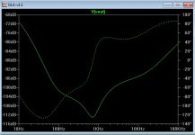
(Attachment 1) is the native PSRR of my GLA amp (Sansui Z3900). Not too bad..
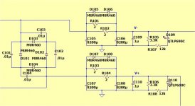
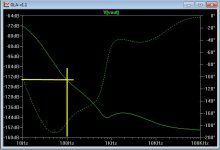
(Attachment 2) is the simulated PSRR at a low power level where no current is being passed through D105-D108
(CRC with diodes schematic - Attachment 3)
Either at higher power levels or with the resistors removed (attachment 4),
the improvement in PSRR remains almost the same .
At low power levels , the power supply has more voltage and just a few
more DB's of ripple rejection at lower frequencies.
I'm designing with Apex Jr's Samwha 8200uf/100V caps , mousers diodes..
http://www.mouser.com/ds/2/115/ds28010-73787.pdf
or
http://www.mouser.com/ds/2/302/BYT79X-600-90443.pdf
10A or 15A , both pads will be on the PCB for these common diode types.
The caps will be 2 or 4 pin 25 or 35mm snap- in type.
I have 8 of the Samwha's already , so my new Badgers will be the first test.
OS
I am building a pair of "honey badgers" and a pair of my new "GLA" amps.
Both have adequate native PSRR .... but , we can do better.
I found the diode bypass of the standard CRC filter as a good solution to the high
current demands of a high power AB amplifier.
(Attachment 1) is the native PSRR of my GLA amp (Sansui Z3900). Not too bad..
(Attachment 2) is the simulated PSRR at a low power level where no current is being passed through D105-D108
(CRC with diodes schematic - Attachment 3)
Either at higher power levels or with the resistors removed (attachment 4),
the improvement in PSRR remains almost the same .
At low power levels , the power supply has more voltage and just a few
more DB's of ripple rejection at lower frequencies.
I'm designing with Apex Jr's Samwha 8200uf/100V caps , mousers diodes..
http://www.mouser.com/ds/2/115/ds28010-73787.pdf
or
http://www.mouser.com/ds/2/302/BYT79X-600-90443.pdf
10A or 15A , both pads will be on the PCB for these common diode types.
The caps will be 2 or 4 pin 25 or 35mm snap- in type.
I have 8 of the Samwha's already , so my new Badgers will be the first test.
OS
Attachments

Thanks man!
For the CRC bypass diodes, here's some options:
MBR1645, rectifier schottky, about 0.3v
MUR820, Fast silicon, about 0.5v
10A1, Standard silicon, about 0.7v
P.S.
Fascinatingly, with any of those diodes, the CRC filter still works. So for my own use, I've changed my "CRC Bypass Diodes" (shown in post#37) to MBR rectifier schottky, 0.3v. This smaller voltage also decreased the price and size of the resistors.
P.P.S.
Also on post 37, another mod done to it was to use the dc umbilical cable instead of the ferrites shown, and then the "output diodes" (far left side of the schematic) ended up mounted onto the amplifier board, and I also changed these to 10A1, plus I increased the amplifier board capacitance to 440u per rail. At this point, perhaps it needs a new schematic. But, there was a heck of a lot more headroom. I don't know why.
Last edited:
- Status
- This old topic is closed. If you want to reopen this topic, contact a moderator using the "Report Post" button.
- Home
- Amplifiers
- Solid State
- CRC power amp supply