A few weeks ago, I asked for suggestions for output devices. Perhaps some of you recall that I once participated in the high end audio market in the late 1970s.
My current company manufactures SHARC based DSP boards. We are currently developing high performance DSP based crossovers.
This has got me thinking again about power amplifiers. I am not saying that Danville Signal is going into the power amplifier business (its possible but not likely). I only bring this up so that you all know I may have a commercial interest at some point.
VA Systems (aka Van Alstine Audio Systems) was founded by myself, Frank Van Alstine and two others. We manufactured power amplifiers and preamplifiers. Perhaps some of you remember these products. I can remember having a conversation with John Curl in our demo room at CES in Chicago. He was working with Levinson in those days.
--- Enough disclosure !!! - On to something interesting....
My current idea is to build a front end module that I can use to drive some arbitrary output stage with.
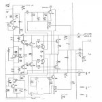
The VA Model 3 used a basic common collector (emitter follower) darlington configuration using what I remember as the JBL T drive circuit. I have attached a pdf of the output stage. We experimented with other output stages. I remember that we did not like the basic common emitter output since it suffers from lack of supply rejection that is intrincically good with a follower. Our version was very hard sounding as I recall.
I always admired Bryston to those days, but their amplifiers always sounded a little hard to me then. I believed they used a common emitter circuit. I found a schematic in Ben Duncan's book, that suggested they used a clever Quad variant that is kind of a common collector - common emitter hybrid. I have also attached a drawing of this circuit.
So here are the discussion points for starters:
1. What do you guys think of the various output topologies and why? I have been thinking of primarily BJT versions but of course, FET and FET BJT hybrids are also popular.
2. Where should a power amplifier clip? In the output stage or someone upstream? If you power the front end with higher supply rails than the output stage, the output stage can saturate.
Al Clark
My current company manufactures SHARC based DSP boards. We are currently developing high performance DSP based crossovers.
This has got me thinking again about power amplifiers. I am not saying that Danville Signal is going into the power amplifier business (its possible but not likely). I only bring this up so that you all know I may have a commercial interest at some point.
VA Systems (aka Van Alstine Audio Systems) was founded by myself, Frank Van Alstine and two others. We manufactured power amplifiers and preamplifiers. Perhaps some of you remember these products. I can remember having a conversation with John Curl in our demo room at CES in Chicago. He was working with Levinson in those days.
--- Enough disclosure !!! - On to something interesting....
My current idea is to build a front end module that I can use to drive some arbitrary output stage with.
The VA Model 3 used a basic common collector (emitter follower) darlington configuration using what I remember as the JBL T drive circuit. I have attached a pdf of the output stage. We experimented with other output stages. I remember that we did not like the basic common emitter output since it suffers from lack of supply rejection that is intrincically good with a follower. Our version was very hard sounding as I recall.
I always admired Bryston to those days, but their amplifiers always sounded a little hard to me then. I believed they used a common emitter circuit. I found a schematic in Ben Duncan's book, that suggested they used a clever Quad variant that is kind of a common collector - common emitter hybrid. I have also attached a drawing of this circuit.
So here are the discussion points for starters:
1. What do you guys think of the various output topologies and why? I have been thinking of primarily BJT versions but of course, FET and FET BJT hybrids are also popular.
2. Where should a power amplifier clip? In the output stage or someone upstream? If you power the front end with higher supply rails than the output stage, the output stage can saturate.
Al Clark
Attachments
Al,
Nice to see you here, thanks for visiting.
Sixtek's comment: takeoff of the bottom outputs should be off the emitter of the driver, not the collector.
I'm with you on the common emitter/source output topologies.
#1 Poor PSRR
#2 Phase shift excacerbated by reactive loads
#3 Offset control limitations
#4 Stability at switch off is questionable.
The good ol' double emitter follower remains the standard in my view.
The Type II EF documented by Doug Self is very good, particularly if the charge suckout across the driver emitters is carefully tuned for the components chosen. This almost completely eliminates crossover artefacts due to switching.
Base stoppers are important, however, as you duly note.
For max power and thus best headroom, it should clip first at the outputs. I favor larger (0.47R) emitter resistors for better quiescent control and current sharing. Smaller, 0.22R, is favored, but current variation is not so good with multiple pairs, and since the resistor is in the fb loop it's size is not too important to damping factor.
High supply rails for the front end is only really beneficial in terms of S/N, because all output stage noise can now be thoroughly decoupled. But it's another pair of windings, more complexity and cost, a lot of people don't bother.
Cheers,
Hugh
AKSA said:Al,
Sixtek's comment: takeoff of the bottom outputs should be off the emitter of the driver, not the collector.
Hugh
It amazing how blind you can get to really stupid errors. I have attached the obvious corrections.
Attachments
danville said:
My current company manufactures SHARC based DSP boards. We are currently developing high performance DSP based crossovers.
Al Clark
I'm sure you also considered a digital amp solution, especially with your DSP front-end and the world focus on efficiency. If you read the threads on "open system" digital and TI's higher frequency digital TAS5261 you might want to keep the analog days behind and develop an all digital solution which DIY'ers could test before a large firm customized for products.
Re: Re: Power Amplifier Output Topologies
Many of our customers are using ICEPOWER switching amplifiers. I think switching amplifiers may be a good practical solution for powered monitors where heat is a big issue.
I am not convinced that switchers make good sense for midrange and tweeter amplifiers. OTOH, you don't need a large power amplifier for the tweeter and midrange. It may be prudent to create hybrid systems of switchers for sub woofers and woofers and linear amplifiers for the higher frequency components.
I have also considered using a switching power supply for the rails of a linear power amplifier. I am not talking about Class G or H. I like the idea of refreshing the supply faster than 100 or 120 Hz. The ideal power supply is a voltage source. You still need to have a very low supply impedance, so this doesn't eliminate good quality capacitors located at the right place, but the capacitors don't need to be nearly as large.
LineSource said:
I'm sure you also considered a digital amp solution, especially with your DSP front-end and the world focus on efficiency. If you read the threads on "open system" digital and TI's higher frequency digital TAS5261 you might want to keep the analog days behind and develop an all digital solution which DIY'ers could test before a large firm customized for products.
Many of our customers are using ICEPOWER switching amplifiers. I think switching amplifiers may be a good practical solution for powered monitors where heat is a big issue.
I am not convinced that switchers make good sense for midrange and tweeter amplifiers. OTOH, you don't need a large power amplifier for the tweeter and midrange. It may be prudent to create hybrid systems of switchers for sub woofers and woofers and linear amplifiers for the higher frequency components.
I have also considered using a switching power supply for the rails of a linear power amplifier. I am not talking about Class G or H. I like the idea of refreshing the supply faster than 100 or 120 Hz. The ideal power supply is a voltage source. You still need to have a very low supply impedance, so this doesn't eliminate good quality capacitors located at the right place, but the capacitors don't need to be nearly as large.
you asked about clipping an amp without saturation. tom holman used a baker clamp in the apt-1 which clipped the output stage within 0.3 or so volts of the supply rails without saturating the output devices. there was no "hangover" at clipping, and the amp actually clipped so cleanly that it was difficult to tell by hearing that the amp had clipped. once the amp was clipped by 2 to 5 percent, then you could begin to hear it. it was not a hard or harsh sounding amp, and it used triple darlington output topology with a baker clamp on the predrivers. the VAS was operated from +/- 75V rails and the predrivers, drivers, and output stage operated from +/- 65V in 8 ohm mode, and +/- 55V in 4 ohm mode. shown below is the "business end" of the apt-1.
Attachments
Dear danville / Mr. Al Clark,
in your AudiogoN letter you wrote:
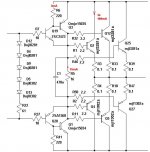
Can you please explain, why the "Output Stage of the VA Systems Model 3" in your pdf-file is exactly half of the "stage" of my Van Alstine Model Two amp ?
Best Regards - Charley
in your AudiogoN letter you wrote:
The model two was an improved modified Dyna Double 400...
...It was always our belief that the Model three was a much better amplifier than the model two.
Can you please explain, why the "Output Stage of the VA Systems Model 3" in your pdf-file is exactly half of the "stage" of my Van Alstine Model Two amp ?
An externally hosted image should be here but it was not working when we last tested it.
Best Regards - Charley
Charley Varrick said:Dear danville / Mr. Al Clark,
in your AudiogoN letter you wrote:
Can you please explain, why the "Output Stage of the VA Systems Model 3" in your pdf-file is exactly half of the "stage" of my Van Alstine Model Two amp ?
Best Regards - Charley
The Model 3 was nominally a 125W amplifier, whereas the Model 2 was about 200-250W. The rails were about 55V & 70V, respectively.
The output transistors are series to increase the voltage swing in the Model 2.
BTW, I don't believe you have a correct schematic. I am replying from memory, I don't have a model 2 schematic.
We did use common collector outputs that were connected series in the Model 2. I believe we used a "JBL" T connection. This means that the emitters of the driver transistors were connected together thrur a R but not connected to ground. We may have use a 16.8 ohm resistor and a series diode for this purpose.
From what I can see of the VAS, it looks different as well. I know for sure that the current mirrors had a diode added to the base bias.
I was fairly certain that there were current mirrors on both the rails.
The Model 2 was really just derived from the Double 400 with a few simple improvements and a lot of repackaging. If you have a Dyna Stereo 400 schematic, you will have a reasonable starting place for an actual schematic.
The Model 3 was a completely new design. The output stage used a common collector (emitter follower) output stage and a bias circuit configured like the schematic that you posted. The voltage tracking transistor was mounted directly on the case of one of the TO-3 output transistors. THIS WAS A BIG DEAL! The bias current tracked quite well as compared to the original Model 2 and most other amplifiers at that time. We went to this approach in the Model 2 later.
We always used common collector output stages at VA. We tried a few common emitter stages but they always sounded harsh to our ears. I had a discussion with Chris Russell at Bryston about this almost 30 years ago. The natural power supply rejection of a common collector is compelling. You do have to supply enough current in the driver transistors to keep the output fast since a capacitive load causes an emitter follower to cutoff.
The VAS was completely different. I haven't decided to share the details yet since I may decide to build a better, more modern version. My company, Danville Signal Processing is manufacturing very high performance DSP based digital crossovers. There is always the possibility that we may build a few amplifier products in the future.
Al Clark
Danville Signal Processing
Dear Mr. Clark,
thank you for your answer.
Let me first say - i have nothing to do with "Electronics" - I am a simple collector - and this was my first post here.
I was always told, that the Model 3 is nothing else than a half Model Two. The Model 3 uses 4 Transistors per Channel - Model Two 8.
The "va systems literature" stated:
We use two computer-grade 20000 microfarad, 75 volt power supply capacitors per channel.
- so the rail voltage is +/- 75 volt for the Model 2 as shown in the circuit diagram.
Even I - as an "electronic laity" - can identify the 1N4004, 2N3773, 2N6609 and TIP42C stuff in the same order in both schematics.
The schematic I pictured is:
Model 2 Power Amp Channel
Drawn by: DAK
Date: 1-31-79
Drawing No.: 750 000 018
On the back plate of my Model Two amp is:
circuit function: DAK 220V/50Hz
mechanical inspection: GB
Listening test: DAKennedy
There is no difference between the schematics and the parts inside.
- And there is no similarity between my Model 2 and a Dyna Double 400 - maybe there was an earlier model ?
YES - I am sure - it is a confusion:
The Absolute Sound issue 9: Dyna Double 400 amp modified by Frank van Alstine and issue 14 Model Two - both amps have nothing in common !
To make a very long story short:
In spring 1980 I received from Mr. David M. from Savage, Minnesota about 25 pages of construction plans and schematics for the Model Two, so my Engineer at the Electronic Lab of the Department of Physics at my former university could service and modify the amp.
3 days ago - when I read the " Dyna Doiuble Story" - I took the Model 2 from my storage room - I have not heard the amp since more than 15 years - there was a lot of dust inside from the back fan.
I connect the amp direct with a little Denon DCP-150 CDPlayer to a pair of old Magnepans - the amp works without error - good amp !
BTW, I have a Model One in my storage room too - do not know if it is working - and I found the schematics:
M 1 Motherboard schematic: Drawing No.: 700 000 010 B
Model 1 Power supply assembly: Drawing No. : 750 000 012
Component Placement: 700 000 012
...only 3 pages.
Thank You - Best Regards from Germany - Charley
thank you for your answer.
Let me first say - i have nothing to do with "Electronics" - I am a simple collector - and this was my first post here.
The Model 3 was nominally a 125W amplifier, whereas the Model 2 was about 200-250W. The rails were about 55V & 70V, respectively.
I was always told, that the Model 3 is nothing else than a half Model Two. The Model 3 uses 4 Transistors per Channel - Model Two 8.
The "va systems literature" stated:
We use two computer-grade 20000 microfarad, 75 volt power supply capacitors per channel.
- so the rail voltage is +/- 75 volt for the Model 2 as shown in the circuit diagram.
Even I - as an "electronic laity" - can identify the 1N4004, 2N3773, 2N6609 and TIP42C stuff in the same order in both schematics.
BTW, I don't believe you have a correct schematic. I am replying from memory, I don't have a model 2 schematic.
The schematic I pictured is:
Model 2 Power Amp Channel
Drawn by: DAK
Date: 1-31-79
Drawing No.: 750 000 018
On the back plate of my Model Two amp is:
circuit function: DAK 220V/50Hz
mechanical inspection: GB
Listening test: DAKennedy
There is no difference between the schematics and the parts inside.
- And there is no similarity between my Model 2 and a Dyna Double 400 - maybe there was an earlier model ?
YES - I am sure - it is a confusion:
The Absolute Sound issue 9: Dyna Double 400 amp modified by Frank van Alstine and issue 14 Model Two - both amps have nothing in common !
To make a very long story short:
In spring 1980 I received from Mr. David M. from Savage, Minnesota about 25 pages of construction plans and schematics for the Model Two, so my Engineer at the Electronic Lab of the Department of Physics at my former university could service and modify the amp.
3 days ago - when I read the " Dyna Doiuble Story" - I took the Model 2 from my storage room - I have not heard the amp since more than 15 years - there was a lot of dust inside from the back fan.
I connect the amp direct with a little Denon DCP-150 CDPlayer to a pair of old Magnepans - the amp works without error - good amp !
BTW, I have a Model One in my storage room too - do not know if it is working - and I found the schematics:
M 1 Motherboard schematic: Drawing No.: 700 000 010 B
Model 1 Power supply assembly: Drawing No. : 750 000 012
Component Placement: 700 000 012
...only 3 pages.
Thank You - Best Regards from Germany - Charley
Charley Varrick said:I was always told, that the Model 3 is nothing else than a half Model Two. The Model 3 uses 4 Transistors per Channel - Model Two 8.
[/B]
This was never true. I know the Model 3 quite well. It started out as my design and was finished by my colleague, Greg Broburg.
We did create a Model 4. It was a mono Model 3. I have 1/2 of the world supply (2 of them). I also have 2 Model 3s.
Charley Varrick said:The "va systems literature" stated:
We use two computer-grade 20000 microfarad, 75 volt power supply capacitors per channel.
- so the rail voltage is +/- 75 volt for the Model 2 as shown in the circuit diagram.
Even I - as an "electronic laity" - can identify the 1N4004, 2N3773, 2N6609 and TIP42C stuff in the same order in both schematics.
The schematic I pictured is:
Model 2 Power Amp Channel
Drawn by: DAK
Date: 1-31-79
Drawing No.: 750 000 018
On the back plate of my Model Two amp is:
circuit function: DAK 220V/50Hz
mechanical inspection: GB
Listening test: DAKennedy
There is no difference between the schematics and the parts inside.
[/B]
You clearly have a Model 2, GB was Greg, DM (Dave) was another partner. I am fairly sure that the schematic is slightly wrong with respect to the current mirror but I haven't actually seen a schematic of this amplifier for almost 30 years now. DAK (Dan Kennedy) manufactures a line of professional audio products (Great River Electronics) that have been well received.
Charley Varrick said:- And there is no similarity between my Model 2 and a Dyna Double 400 - maybe there was an earlier model ?
YES - I am sure - it is a confusion:
The Absolute Sound issue 9: Dyna Double 400 amp modified by Frank van Alstine and issue 14 Model Two - both amps have nothing in common !
[/B]
Van Alstine Audio Systems (aka VA Systems) was founded by Frank Van Alstine, Greg Broburg, Dave M and myself). Dave & Frank modified the Dyna 400 to create the Double 400.
The Model 2 was largely a repackaged Double 400. It had a few minor changes to the Double 400 schematic. You can compare a Dyna 400 and the schematic you have and see the similarities. We also used much better parts than Dyna. The biggest difference was the improved current mirror that does not show up in the schematic that you presented. I don't know why.
In the days of this amplifier, the board layout was independent of the schematic. The schematic you have was drawn after the fact so it may just be a mistake.
Charley Varrick said:To make a very long story short:
In spring 1980 I received from Mr. David M. from Savage, Minnesota about 25 pages of construction plans and schematics for the Model Two, so my Engineer at the Electronic Lab of the Department of Physics at my former university could service and modify the amp.
3 days ago - when I read the " Dyna Doiuble Story" - I took the Model 2 from my storage room - I have not heard the amp since more than 15 years - there was a lot of dust inside from the back fan.
I connect the amp direct with a little Denon DCP-150 CDPlayer to a pair of old Magnepans - the amp works without error - good amp !
BTW, I have a Model One in my storage room too - do not know if it is working - and I found the schematics:
M 1 Motherboard schematic: Drawing No.: 700 000 010 B
Model 1 Power supply assembly: Drawing No. : 750 000 012
Component Placement: 700 000 012
...only 3 pages.
Thank You - Best Regards from Germany - Charley [/B]
Greg Broburg and I designed the Model 1. The phono circuit was patented.
Al Clark
djk said:It works best if the drivers are biased real hard.
Yes, at least at 15% output idle power
In reviewing the schematic va3_output.pdf of the VA Model 3, methinks that there is a mistake here at the node: base of the 2N6609s. Als schematic shows them tied to minus V instead of the emitter of the TIP42C. To throw a little more into the pot here, my opinion is that clipping is not a first order problem. The effects of stored charge in the output devices are.
Greg
Greg
- Status
- This old topic is closed. If you want to reopen this topic, contact a moderator using the "Report Post" button.
- Home
- Amplifiers
- Solid State
- Power Amplifier Output Topologies